
Breathing machine mask

A ventilator and mask technology, applied in the field of ventilator masks, can solve problems such as increased learning costs for nursing staff or family members, impact on collection, and inability for timely adjustment by nursing staff, so as to improve the convenience and reliability of use and reduce manpower and material costs, and the effect of improving the accuracy of eye tracking

Pending Publication Date: 2022-05-20
BEIJING 7INVENSUN TECH +1
View PDF0 Cites 0 Cited by
  • Summary
  • Abstract
  • Description
  • Claims
  • Application Information

AI Technical Summary

Problems solved by technology

[0005] As a result, the way that existing sick user groups use the eye-control all-in-one machine requires nursing staff to accompany them for long-term care, and to operate and adjust the eye-control all-in-one machine according to the needs of sick users at any time, which will not only cause the nurses Or the learning costs of family members increase, the use efficiency of the eye control all-in-one machine decreases, and the nursing staff cannot make timely adjustments, which will also affect the user experience of the sick user.
Moreover, the condition and usage habits of some patients determine that during the use of the eye control all-in-one machine, the patient will need to move or change the posture of the body at regular intervals, resulting in a large deviation between the position of the eyes and the calibration position due to position changes or even The eye image is already within the image capture range, and the eye control operation is not good or even unusable; at the same time, for patients wearing ventilator masks, the ventilator masks may partially cover the vicinity of the eyes, thereby affecting The camera of the eye control all-in-one machine collects eye movement data, which increases the difficulty of tracking the user's line of sight, and even fails the line of sight tracking.

Method used


Image

  • Breathing machine mask
  • Breathing machine mask
  • Breathing machine mask

Examples


Embodiment Construction

[0035] The present invention will be further described in detail below in conjunction with the accompanying drawings and embodiments. It should be understood that the specific embodiments described here are only used to explain the present invention, but not to limit the present invention. In addition, it should be noted that, for the convenience of description, only some structures related to the present invention are shown in the drawings but not all structures.

[0036] In the description of the present invention, unless otherwise clearly specified and limited, the terms "connected", "connected" and "fixed" should be understood in a broad sense, for example, it can be a fixed connection, a detachable connection, or an integrated ; It can be a mechanical connection or an electrical connection; it can be a direct connection or an indirect connection through an intermediary, and it can be the internal communication of two components or the interaction relationship between two ...


PUM


Abstract

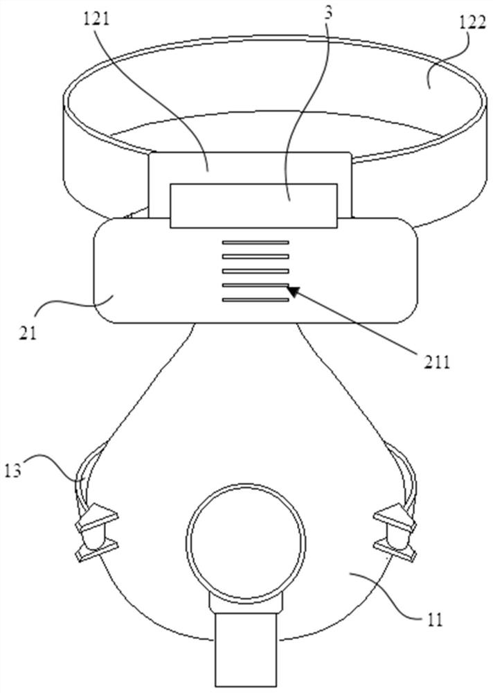
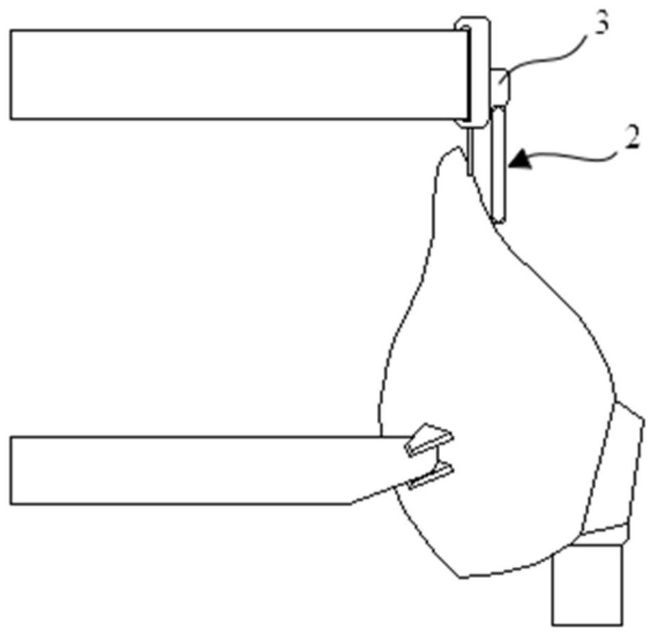
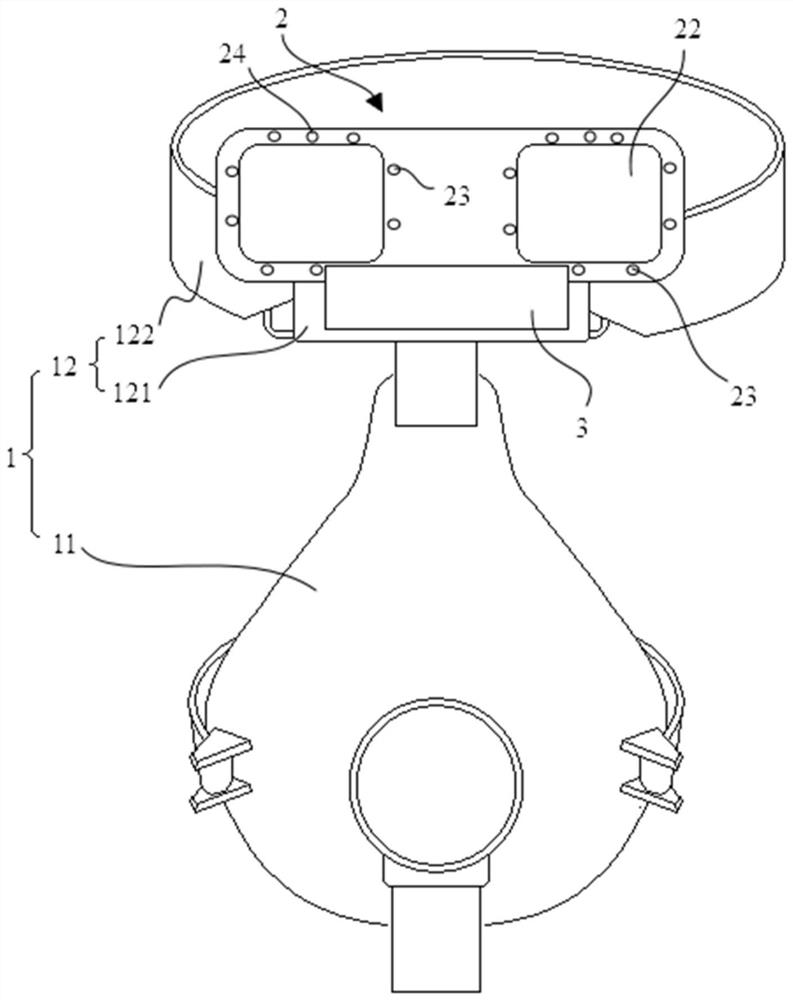
The invention belongs to the technical field of eyeball tracking, and particularly discloses a respirator mask. The breathing machine mask comprises a mask body, wherein the mask body comprises a mask and a head band which are connected with each other; the eye control device is connected with the head band, the eye control device comprises a display module and an eyeball tracking module, and the eyeball tracking module is used for tracking a fixation point or a fixation direction of a user so as to control operation of the display module; the eye control device is provided with a first position where the display module is located right in front of the user and a second position where the display module is located outside the sight line of the user. According to the respirator mask disclosed by the invention, the use convenience and use reliability of a user wearing the respirator mask to the eye control device can be improved, so that the user wearing the respirator mask can conveniently and effectively communicate with the outside.

Description

technical field [0001] The invention relates to the technical field of eye tracking, in particular to a ventilator mask. Background technique [0002] Eye tracking technology is a technology that uses mechanical, electronic, optical and other detection methods to obtain the user's current gaze point or gaze direction. With the rapid development of computer vision, artificial intelligence technology and digital technology, eye tracking technology has become a current hot research field, and has a wide range of applications in the field of human-computer interaction, for example, it can be applied to communication aids, vehicle assisted driving, virtual reality , remote monitoring, eye movement and psychological analysis, cognitive impairment diagnosis, etc. [0003] The eye control all-in-one machine is a product that combines a binocular eye control device with a tablet computer. Compared with the original plug-in eye control device, it is more portable and easier to instal...

Claims


Application Information

Patent Timeline
Patent Type & Authority Applications(China)
IPC IPC(8): A61M16/06G06F3/01G06V40/18G06F3/14
CPCA61M16/06A61M16/0683G06F3/013G06F3/1454
Inventor 王全黄通兵其他发明人请求不公开姓名
Owner BEIJING 7INVENSUN TECH
Learn More