Multipurpose landscape building
A multi-purpose, landscape technology, applied in the direction of public buildings, buildings, building components, etc., can solve the problem of single use function, and achieve the effect of increasing usable functions, convenient driving and simple structure
- Summary
- Abstract
- Description
- Claims
- Application Information
AI Technical Summary
Problems solved by technology
Method used
Image

Examples
Embodiment 1
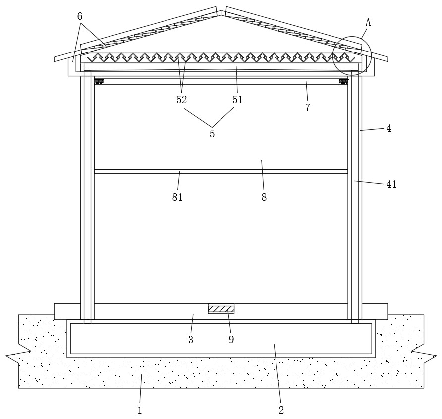
[0031] see figure 1 , figure 2 and Figure 4 As shown, the present invention provides the following technical solutions: a multi-purpose landscape building, comprising a landscape building main body arranged on the top of the soil layer 1, and the landscape building main body includes a water storage tank 2, a floor layer 3, a column 4 and rainwater collection device 5;
[0032] The water storage tank 2 is pre-buried in the soil layer 1; specifically, in practical application, the water storage tank 2 can be connected with the water supply system of the scenic spot, and a filter screen and other structures can be set at the water outlet of the water storage tank 2. This can utilize the rainwater collected by the landscape architecture provided by the present invention to irrigate the overall scenic area, thereby effectively realizing the recycling of rainwater;
[0033] The floor layer 3 is arranged on the top of the water storage tank 2, and the top surface of the floor l...
Embodiment 2
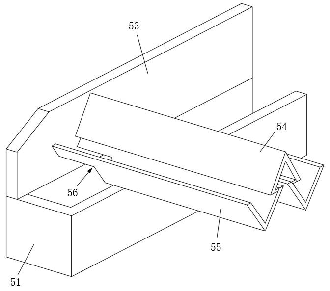
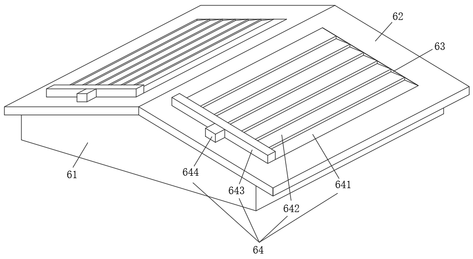
[0043] see Figure 1-Figure 4 As shown, on the basis of the first embodiment above, in this embodiment, a ceiling 6 is fixed on the top of the column 4, and the ceiling 6 includes a base 61 and two inclined plates 62 symmetrically fixed on the top of the base 61. Mounting holes 63 are opened on the board 62 , and a rainfall adjustment device 64 is embedded in the two mounting holes 63 .
[0044] In this embodiment, the above-mentioned rainfall adjustment device 64 includes:
[0045] Fixing blocks 641 fixed on the upper / lower ends of the mounting hole 63;
[0046] A plurality of rotating plates 642 arranged between two fixed blocks 641;
[0047]The transmission box 643 and the drive motor 644 fixed on the top of the swash plate 62 ; the drive motor 644 synchronously drives the rotating plate 642 to rotate through the transmission box 643 .
[0048] Further, a plurality of rotating plates 642 are overlapped end to end, and the top of the rotating plate 642 matched with the fi...
Embodiment 3
[0056] see Figure 1-Figure 4 As shown, on the basis of the above-mentioned embodiment 1 or embodiment 2, in this embodiment, a roller blind device is provided between every two adjacent columns 4, and the roller blind device includes at least a rotatable shaft 7 and a winding shaft 7. The roller blind 8 on the rotating shaft 7.
[0057] Further, a slide plate 81 is provided at the bottom of each roller blind 8 , and the slide plate 81 is slidably fitted between two adjacent columns 4 .
[0058] Furthermore, both ends of the rotating shaft 7 are provided with return springs, the slide plate 81 is a permanent magnet plate, and four detachable electromagnetic blocks 9 are embedded in the top of the floor layer 3, and the four electromagnetic blocks 9 attract four magnets respectively when energized. 81 skateboards.
[0059] Cooperate with the above-mentioned rainwater collection device 5, drive the electromagnetic block 9 to attract the slide plate 81 to move downward in windy...
PUM
 Abstract
Description
Claims
Application Information
 - R&D
- Intellectual Property
- Life Sciences
- Materials
- Tech Scout
- Unparalleled Data Quality
- Higher Quality Content
- 60% Fewer Hallucinations
Browse by: Latest US Patents, China's latest patents, Technical Efficacy Thesaurus, Application Domain, Technology Topic, Popular Technical Reports.
© 2025 PatSnap. All rights reserved.Legal|Privacy policy|Modern Slavery Act Transparency Statement|Sitemap|About US| Contact US: help@patsnap.com