Distributed energy storage system and control method thereof

A distributed energy storage and energy storage technology, applied in battery temperature control, electrical components, electrochemical generators, etc., can solve problems such as increased power consumption, difficult maintenance, and increased number of cooling devices

Pending Publication Date: 2022-05-20
SUNGROW ENERGY STORAGE TECH CO LTD
View PDF6 Cites 1 Cited by
  • Summary
  • Abstract
  • Description
  • Claims
  • Application Information

AI Technical Summary

Problems solved by technology

[0002] At present, the cooling device used for supporting the energy storage battery cabinet is generally integrated inside each battery cabinet. The disadvantages are: 1) In the scenario of centralized installation of large energy storage batteries, there are a large number of battery cabinets, and each battery cabinet is integrated with a set of cooling devices. Or multiple sets of cooling devices, resulting in an proportional increase in the number of supporting cooling devices, and the cost is too high; 2) The battery cabinet and cooling device must be transported as a whole, and the transportation plan is not flexible; 3) The cooling device is located in the battery cabinet, reducing the battery cabinet 4) The cooling device inc

Method used


Image

  • Distributed energy storage system and control method thereof
  • Distributed energy storage system and control method thereof
  • Distributed energy storage system and control method thereof

Examples


Embodiment 1

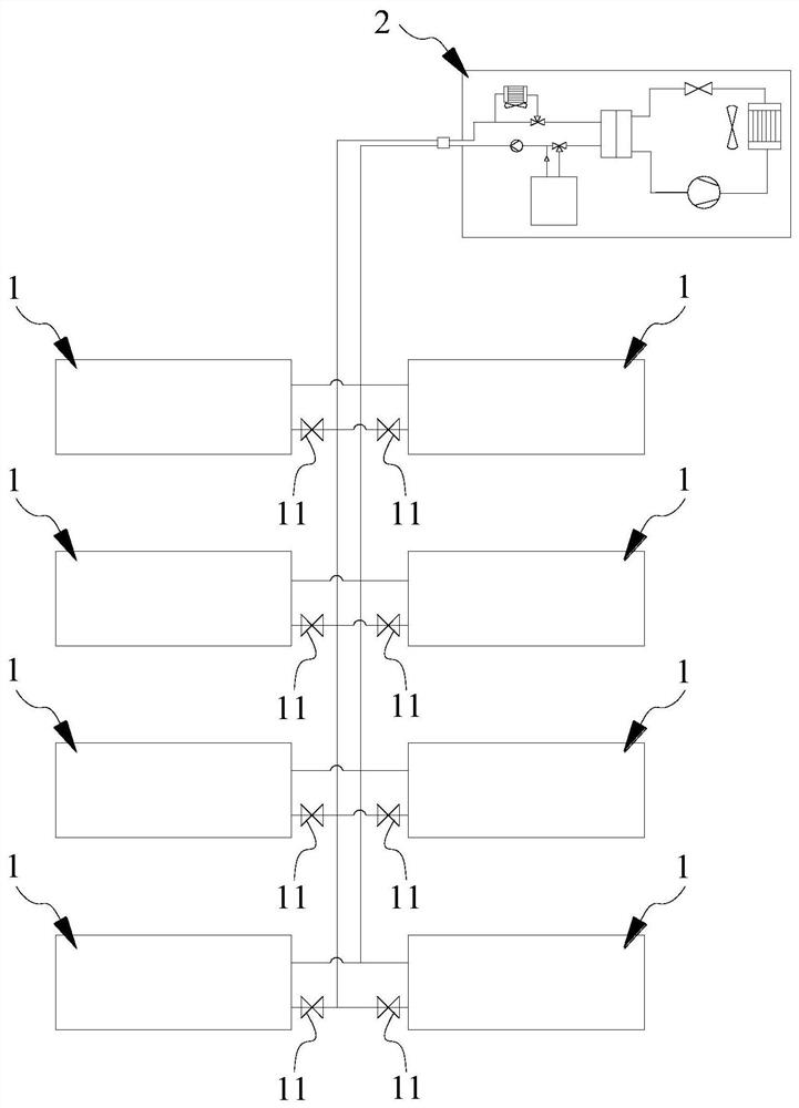
[0041] As mentioned in the background technology section, the cooling devices used in conventional energy storage battery cabinets are generally integrated inside the battery cabinets. In the scenario where energy storage battery Occupying the internal space of the energy storage battery cabinet will lead to a decrease in the space utilization rate and energy efficiency of the energy storage battery cabinet; at the same time, it will also increase the weight and volume of the energy storage battery cabinet. Both will cause adverse effects; and, due to the limitation of the internal space of the energy storage battery cabinet, the volume of the cooling device will be small, and the heat dissipation environment of the cooling device will be poor, so that the heat transfer performance of the cooling device will also decrease, and the cooling efficiency will be lower. Low, at the same time, is also not conducive to maintenance.

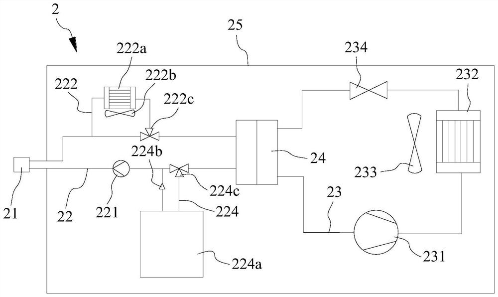
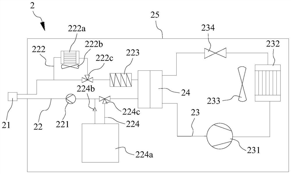
[0042] To this end, the present invention provides ...

Embodiment 2

[0081] Please refer to Figure 4-Figure 8 , Figure 4 It is a schematic flow chart of the control method of the distributed energy storage system provided by the present invention, Figure 5 It is a schematic flow chart of the first specific implementation manner of step S2, Figure 6 It is a schematic flow chart of the second specific implementation manner of step S2, Figure 7 It is a schematic flow chart of the third specific implementation manner of step S2, Figure 8 It is a schematic flowchart of the fourth specific implementation manner of step S2.

[0082] The present invention also provides a control method for a distributed energy storage system, which is applicable to the distributed energy storage system involved in the various implementations of the first embodiment. In this way, the descriptions of the structure, technical effects and related parameters (such as the temperature of the first device and the temperature of the second device) of the distributed e...


PUM


Abstract

The invention discloses a distributed energy storage system and a control method thereof.The distributed energy storage system comprises a plurality of energy storage cabinets and independently arranged heat exchange devices, each energy storage cabinet is internally provided with an energy storage device and a heat exchange channel, and each heat exchange device is provided with an interface component; the heat exchange channels of all the energy storage cabinets are connected into the interface component in parallel, and the heat exchange device provides heat exchange media for all the heat exchange channels through the interface component. The heat exchange device in the distributed energy storage system is independently arranged, so that structural design, transportation and the like of the heat exchange device and the energy storage cabinet do not interfere with each other, and the performance of the heat exchange device and the energy storage cabinet can be guaranteed.

Description

technical field [0001] The invention relates to the technical field of heat exchange, in particular to a distributed energy storage system and a control method thereof. Background technique [0002] At present, the cooling device used for supporting the energy storage battery cabinet is generally integrated inside each battery cabinet. The disadvantages are: 1) In the scenario of centralized installation of large energy storage batteries, there are a large number of battery cabinets, and each battery cabinet is integrated with a set of cooling devices. Or multiple sets of cooling devices, resulting in an proportional increase in the number of supporting cooling devices, and the cost is too high; 2) The battery cabinet and cooling device must be transported as a whole, and the transportation plan is not flexible; 3) The cooling device is located in the battery cabinet, reducing the battery cabinet 4) The cooling device increases the overall weight of the battery cabinet, whic...

Claims


Application Information

Patent Timeline
IPC IPC(8): H01M10/613H01M10/615H01M10/627H01M10/63H01M10/6563H01M10/6566H01M10/6568
CPCH01M10/613H01M10/615H01M10/627H01M10/63H01M10/6563H01M10/6568H01M10/6566Y02E60/10
Inventor 柳家庆
Owner SUNGROW ENERGY STORAGE TECH CO LTD
Why Eureka
Try Eureka