
Wireless transmission system network self-optimization method based on channel quality monitoring

A technology of wireless transmission and channel quality, applied in transmission systems, transmission monitoring, wireless communication, etc., can solve problems such as data congestion, huge post-maintenance costs, hindering the development of industrial wireless transmission systems, etc., and reduce the level of radio frequency interference and reduce The effect of on-site data loss and automatic optimization of network failures

Pending Publication Date: 2022-05-20
SHENYANG ZHONGKE AOWEI SCI & TECH CO LTD
View PDF0 Cites 0 Cited by
  • Summary
  • Abstract
  • Description
  • Claims
  • Application Information

AI Technical Summary

Problems solved by technology

It is precisely because the industrial wireless transmission network is used in harsh, complex, and changeable environments in the wild. From the completion of deployment to the operation of the system, the stable period usually does not exceed one year, and various transmission problems will occur. On-site maintenance and troubleshooting of wireless transmission systems
The maintenance and investigation of the existing system is carried out manually. Usually, 2-3 technicians are required to take a lift truck to the site to re-align the antenna or re-select the central station. The equipment The nearest distance between the installation site and the urban area is more than 40 kilometers, and the maintenance cost is usually 3,000 to 5,000 yuan. The system maintenance has generated a huge amount of maintenance costs, which is also the main factor hindering the further development of industrial wireless transmission systems in the industrial industry.
[0005] According to many years of experience in wireless transmission system maintenance, there are three main reasons for the above failures: 1. The change of the natural environment makes the wireless communication of the equipment in the system change from visible transmission to invisible transmission. The growth of new branches and leaves of trees blocks the original wireless transmission path, and the new tall buildings block the original wireless transmission path. These are the reasons why wireless communication changes from visible transmission to invisible transmission; 2. Central station The downtime caused a large area of ​​data loss. Usually, a central station will access the data of dozens or even hundreds of WIA-FA remote wireless transmission units, and a WIA-FA remote wireless transmission unit carries hundreds of For the data transmission task of an on-site monitoring point, when there is a power outage at the central station and the central equipment is down, it means that thousands of points of data are lost, and the scope of influence is extensive.
3. The unreasonable signal radiation of the newly built wireless transmission system and the radio frequency interference of the established system usually do not interrupt the transmission between devices, but lead to a decrease in the transmission bandwidth of the system, which in turn leads to data congestion and data loss

Method used

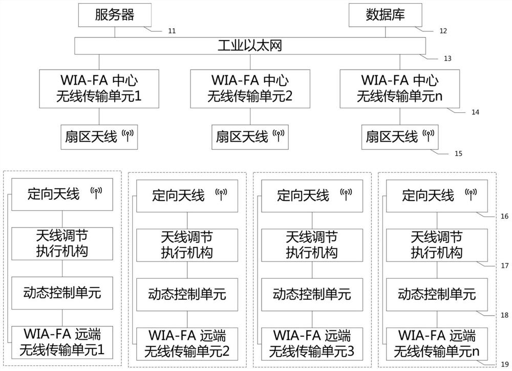
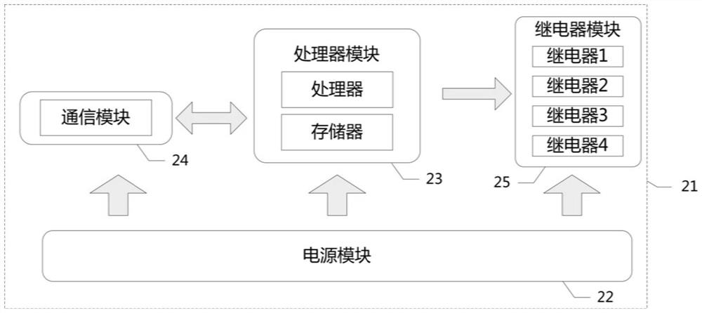
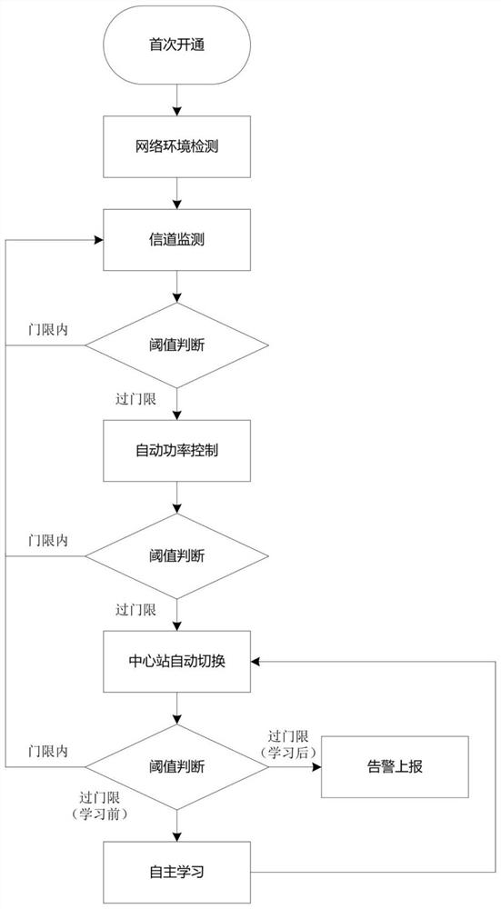

Image

  • Wireless transmission system network self-optimization method based on channel quality monitoring
  • Wireless transmission system network self-optimization method based on channel quality monitoring
  • Wireless transmission system network self-optimization method based on channel quality monitoring

Examples


Embodiment Construction

[0087] The present invention will be further described in detail below in conjunction with the accompanying drawings and embodiments.

[0088] In order to make the above-mentioned purpose, features and advantages of the present invention more obvious and understandable, the specific implementation manners of the present invention will be described in detail below in conjunction with the accompanying drawings. In the following description, numerous specific details are set forth in order to provide a thorough understanding of the present invention. However, the present invention can be implemented in many other ways different from those described here, and those skilled in the art can make similar improvements without violating the connotation of the invention, so the present invention is not limited by the specific implementation disclosed below.

[0089] Unless otherwise defined, all technical and scientific terms used herein have the same meaning as commonly understood by on...


PUM


Abstract

The invention relates to the field of industrial wireless transmission systems, in particular to a network self-maintenance method for automatically maintaining a network and guaranteeing a transmission rate based on radio frequency channel quality monitoring. Comprising the following steps that a dynamic control unit continuously monitors channel information of connection between a WIA-FA far-end wireless transmission unit and a WIA-FA center wireless transmission unit, automatic power control is carried out on the WIA-FA far-end wireless transmission unit according to the monitored channel information condition, and when the channel quality cannot be improved through power control, the WIA-FA far-end wireless transmission unit is switched to the WIA-FA far-end wireless transmission unit is switched to the WIA-FA center wireless transmission unit. And controlling the antenna adjustment execution mechanism to adjust the horizontal angle of the antenna, and switching the WIA-FA far-end wireless transmission unit to the standby WIA-FA central wireless transmission unit and performing automatic alignment of the antenna. And when the channel quality cannot be improved by switching the central station, executing an autonomous learning process, refreshing an access neighbor table, autonomously switching the central station, and completing antenna alignment and automatic power control. According to the invention, the labor cost is effectively reduced, the network maintenance efficiency is improved, and the network fault time is shortened, so that the transmission stability of the industrial wireless transmission system is ensured.

Description

technical field [0001] The invention relates to a self-maintenance method of an industrial wireless transmission system, in particular to a network self-optimization method of a wireless transmission system based on channel quality monitoring. Background technique [0002] In recent years, industrial data acquisition and control systems based on wireless technology have been increasingly perfected, and factory intelligent construction projects have developed rapidly. With the continuous evolution of technology, the requirements for low latency and high bandwidth of the transmission network in the system are also increasing. The industrial wireless transmission system is more and more applied to the construction of industrial digitalization projects due to its advantages of convenient deployment, low construction cost, and no need to stop production deployment. As the backbone transmission network, the industrial wireless transmission system plays an important role in the ent...

Claims


Application Information

Patent Timeline
IPC IPC(8): H04W24/02H04W24/04H04B17/318H04B17/309H01Q3/02H01Q3/00H01Q1/24
CPCH04W24/02H04W24/04H04B17/309H04B17/318H01Q1/241H01Q1/246H01Q3/005H01Q3/02Y02D30/70
Inventor 张阳阳刘炳良韩冬月张新迎曹忠巍赵雪峰
Owner SHENYANG ZHONGKE AOWEI SCI & TECH CO LTD
Learn More