Lifting platform material pushing box device for improving production efficiency of power battery raw materials
A technology of production efficiency and power battery, applied in the direction of lifting device, lifting frame, transportation and packaging, etc., can solve the problems such as shaking, reducing the operation safety of the lifting table pushing box device, and spilling battery raw materials.
- Summary
- Abstract
- Description
- Claims
- Application Information
AI Technical Summary
Problems solved by technology
Method used
Image
Examples
Embodiment 1
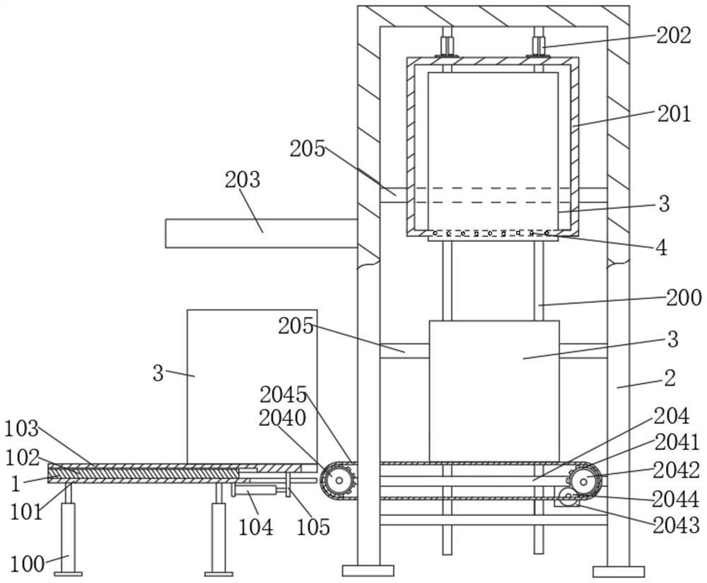
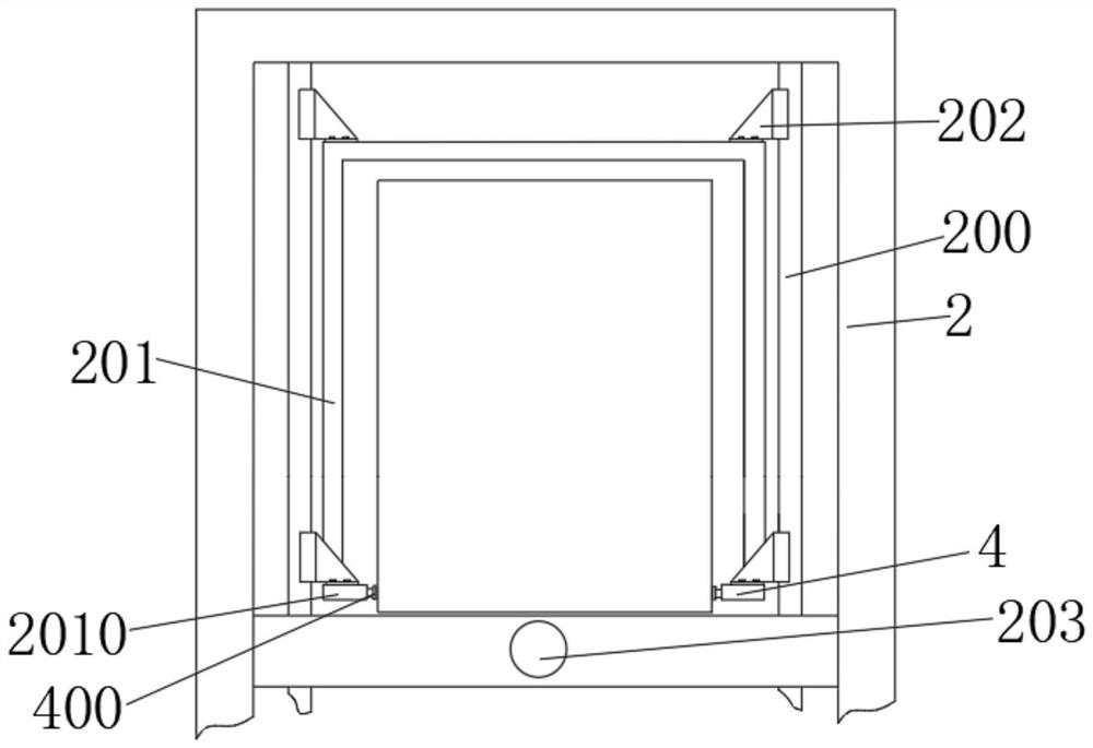
[0038] The embodiment of the present invention provides a lifting table pushing box device for improving the production efficiency of power battery raw materials, including a loading assembly 1 and a lifting frame 2, and the loading assembly 1 is used to send the material box 3 to the The lifting frame 2 is fixedly connected with a guide rail 200 , and a material box clamping frame 201 is slidably connected to the guide rail 200 , and the material box clamping frame 201 is used for clamping the material box 3 .
[0039] The working principle and beneficial effects of the above technical solutions are as follows: the feeding assembly 1 pushes the material box 3 onto the lifting frame 2, and then the material box clamping frame 201 clamps the material box 3, The cartridge clamping frame 201 slides upward along the guide rail 200 to move the cartridge 3 upward, thereby realizing the lifting and transportation of the cartridge 3. Compared with the direct use of ropes, the design of...
Embodiment 2
[0042] On the basis of the above Embodiment 1, the cartridge clamping frame 201 is bolted with a guide block 202, the guide block 202 is slidably connected to the guide rail 200, and the guide block 202 is provided with a first drive component, the first driving component is used to drive the guide block 202 to slide along the guide rail 200;
[0043] The lifting frame 2 is provided with a material box pushing cylinder 203;
[0044] The feeding assembly 1 includes a bracket leg 100, a fixed plate 101 is fixedly connected to the bracket leg 100, a push plate guide rail 102 is fixedly connected to the fixed plate 101, and a movable plate is slidably connected to the push plate guide rail 102. 103, a cylinder 104 is fixedly connected to the bottom of the fixing plate 101, and one end of the cylinder 104 away from the fixing plate 101 is fixedly connected to the moving plate 103 through a connecting plate 105;
[0045] A placing table 204 is fixedly connected to the lifting frame...
Embodiment 3
[0049] On the basis of Embodiment 1 or 2, the cartridge clamping frame 201 is provided with two sets of symmetrically arranged clamping assemblies 4, and the clamping assemblies 4 are used to clamp the cartridge 3;
[0050] The clamping assembly 4 includes a plurality of clamping bodies 400 evenly arranged along the lower frame 2010 of the cartridge clamping frame 201;
[0051] The clamping body 400 includes a plurality of mounting shells 4000 , and the mounting shells 4000 are evenly and fixedly connected in the lower frame 2010 . The body 401 includes a coarse adjustment assembly 402, a clip-on execution head 402 and a fine adjustment assembly 403 installed in the clip-on execution head 402;
[0052] The coarse adjustment assembly 402 includes a screw shaft 4020 , the screw shaft 4020 is rotatably connected in the clamping body 400 , and the screw shaft 4020 is provided with a left-hand thread 4021 and a right-hand thread 4022 . The lever shaft 4020 is threadedly connected ...
PUM
 Abstract
Description
Claims
Application Information
 - R&D
- Intellectual Property
- Life Sciences
- Materials
- Tech Scout
- Unparalleled Data Quality
- Higher Quality Content
- 60% Fewer Hallucinations
Browse by: Latest US Patents, China's latest patents, Technical Efficacy Thesaurus, Application Domain, Technology Topic, Popular Technical Reports.
© 2025 PatSnap. All rights reserved.Legal|Privacy policy|Modern Slavery Act Transparency Statement|Sitemap|About US| Contact US: help@patsnap.com


