Air flow measuring method based on bell mouth flow tube speed distribution model

A speed distribution and air flow technology, applied in the direction of instrumentation, design optimization/simulation, calculation, etc., can solve the problems of multiple measuring point layout and high cost, reduce the number of measuring points, accurately arrange them, improve flow measurement accuracy and measurement efficiency Effect

Active Publication Date: 2022-05-24
BEIJING CHANGCHENG INST OF METROLOGY & MEASUREMENT AVIATION IND CORP OF CHINA
View PDF5 Cites 2 Cited by
  • Summary
  • Abstract
  • Description
  • Claims
  • Application Information

AI Technical Summary

Problems solved by technology

[0006] In order to solve the problems of many measuring points and high costs of labor, time, and technology, the main purpose of the present invention is to provide a flow measurement method based on the velocity distribution model of the bell-shaped flow tube, and determine the test flow rate according to the velocity distribution model in the tube. The distribution range of the pressure measurement rake on the middle measurement section, and then measure the data of a small number of points on the measurement section to obtain a complete velocity distribution model in the pipe, and perform integral calculation on the obtained complete velocity distribution model in the pipe to obtain the air flow in the pipe. For the measurement of air intake flow of aeroengines, improve the accuracy and efficiency of flow measurement

Method used


Image

  • Air flow measuring method based on bell mouth flow tube speed distribution model
  • Air flow measuring method based on bell mouth flow tube speed distribution model
  • Air flow measuring method based on bell mouth flow tube speed distribution model

Examples


Embodiment 1

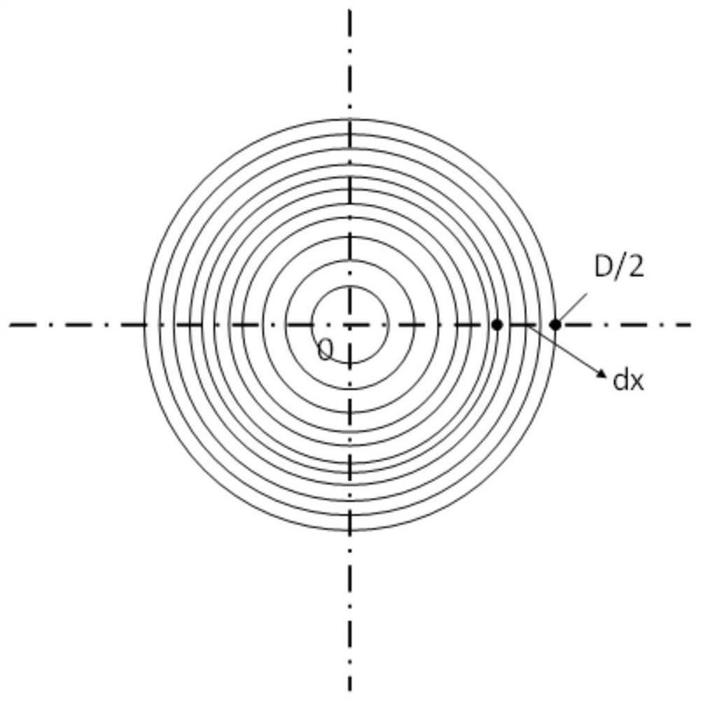
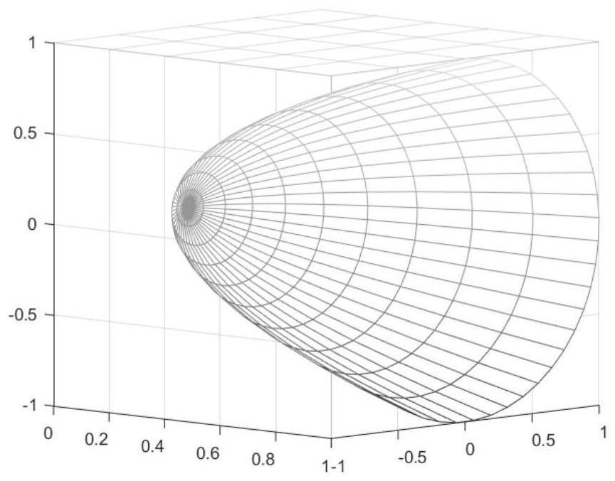
[0060] In order to solve the problem of many measuring points when using the bell-shaped flow tube to accurately measure the air flow, the diameter of the pipe is D=400mm, the profile section is a twisted pair profile, and the polar coordinate formula of the twisted pair is ρ 2 =r 2 In cos 2θ, r is taken as 0.637D, and a bell-shaped flow tube with a flanging structure of 40mm is taken as an example, and the on-site air flow measurement process using this bell-shaped flow tube is described. At the same time, the annular area method was used to measure the air flow under the same flow state, and the two results were compared and analyzed.

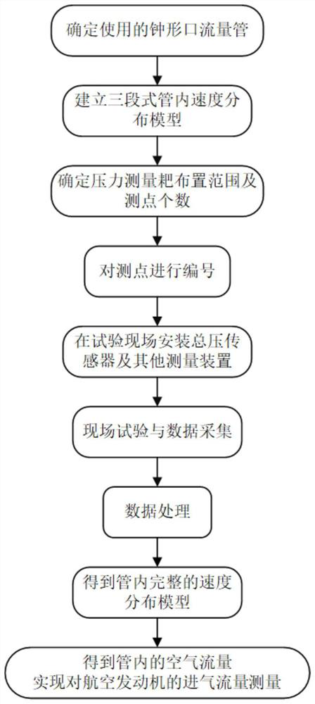
[0061] like figure 1 As shown, the specific implementation steps of the flow measurement method based on the velocity distribution model of the bell-shaped flow tube disclosed in this embodiment are as follows:

[0062] Step 1: For the bell-shaped flow tube used, establish a velocity distribution model in the tube, and determine the arrang...


PUM


Abstract

The invention discloses an air flow measurement method based on a bell mouth flow tube speed distribution model, and belongs to the field of aero-engine air inlet flow measurement. The implementation method comprises the steps of determining a point distribution range of a pressure measurement rake on a measurement section in a test according to an in-pipe speed distribution model, then performing data measurement of a small number of points on the measurement section to obtain an in-pipe complete speed distribution model, performing integral calculation on the obtained in-pipe complete speed distribution model to obtain in-pipe air flow, and calculating the in-pipe air flow according to the in-pipe air flow. And the air inlet flow of the aero-engine is measured. According to the method, the in-pipe velocity distribution model is divided into the constant section, the linear section, the logarithmic section and the velocity distribution characteristics of all the sections, the point distribution range and the point distribution number of the pressure measurement rakes on the measurement section for calibrating the in-pipe velocity distribution model are selected in a segmented mode, accurate measurement point distribution is achieved, the number of measurement points can be reduced, and the measurement accuracy is improved. On the premise that the measurement precision of the air inlet flow of the aero-engine is guaranteed, the flow measurement precision and the measurement efficiency are improved.

Description

technical field [0001] The invention belongs to the field of aero-engine intake air flow measurement, and relates to an air flow measurement method based on a velocity distribution model of a bell-shaped flow tube. Background technique [0002] The air intake flow measurement results of aero-engines are often used for performance evaluation and condition monitoring of the whole engine and components. The most commonly used measurement scheme is to rely on the bell-shaped flow tube equipped with a total static pressure probe for measurement, and this measurement method is currently used. There are the following two implementations. [0003] One is to set fewer measuring points for simple measurement, and obtain the flow rate in the pipe through the average of a few measuring points. This solution cannot reflect the true pressure and velocity distribution in the tube, resulting in inaccurate measurement results. [0004] The other is to obtain the air flow in the tube by the...

Claims


Application Information

Patent Timeline
Patent Type & Authority Applications(China)
IPC IPC(8): G06F30/28G06F113/08
CPCG06F30/28G06F2113/08Y02T90/00
Inventor 余楠兮王毅刘琳琳王玉芳杨振
Owner BEIJING CHANGCHENG INST OF METROLOGY & MEASUREMENT AVIATION IND CORP OF CHINA
Why Eureka
Try Eureka