Cable pulling and arranging equipment

A cable and pull wire technology, applied in the field of cable pull and wire arrangement equipment, can solve the problems of cumbersome cable tray construction process, and achieve the effects of avoiding separation from the cable tray, wide application range, and reasonable structure

Pending Publication Date: 2022-05-24
KUNMING UNIV OF SCI & TECH +1
View PDF0 Cites 0 Cited by
  • Summary
  • Abstract
  • Description
  • Claims
  • Application Information

AI Technical Summary

Problems solved by technology

[0003] The present invention aims at the problems such as the cumbersome construction process of the cable bridge in the prior art, and provides a cable pulling and arranging device, which drives the gear to move on the rack through the servo motor, and drives the guide rail slider trolley to move along the cable bridge body, thereby Drive the cables fixed on the cable device to be transported to the end of the cable tray body in a regular manner. The structure is reasonable, the operation is simple, and the scope of application is wider.

Method used


Image

  • Cable pulling and arranging equipment
  • Cable pulling and arranging equipment
  • Cable pulling and arranging equipment

Examples


Embodiment 1

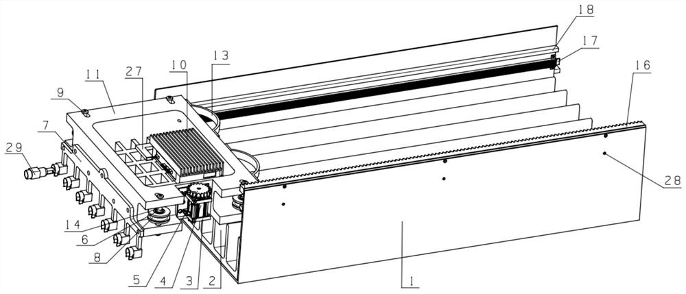
[0046] Embodiment 1: A kind of cable drawing line arrangement equipment (see Figure 1-5 ), including the cable tray body 1 and the guide rail slider trolley 11,

[0047] The bottom of the cable tray body 1 is evenly provided with several wire grooves 2 along the extension direction of the bridge frame. A rack 16 is arranged on one side wall of the cable tray body 1 along the extension direction of the bridge frame. Guide rails 18 are arranged opposite to the extending direction of the bridge;

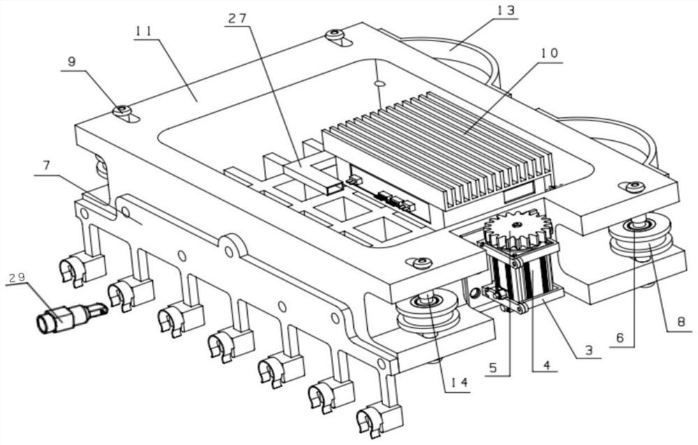
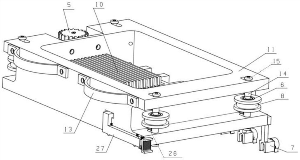
[0048] The outer walls on both sides of the guide rail slider trolley 11 are provided with grooved wheels 8, and the guide rail 18 on the cable bridge body 1 is embedded in the groove of the grooved wheel 8 corresponding to the grooved wheel 8, and the grooved wheel 8 is rollingly connected with the guide rail 18. The side end of the guide rail slider trolley 11 is provided with a servo motor 4, the output shaft of the servo motor 4 is provided with a gear 5, the gear 5 is engaged wit...

Embodiment 2

[0050] Embodiment 2: The structure of the cable pulling and arranging equipment in this embodiment is basically the same as that of the cable pulling and arranging equipment in Embodiment 1. A plurality of pin slots, the end of the cable is fixedly provided with a line card 29, and the line card 29 is stuck in the pin slot of the wire pulling device 7;

[0051] Tightening bolts passing through the wall of the line card are evenly arranged on the line card 29 along the circumferential direction, and the ends of the cables can be fixed in the line card 29 by tightening the bolts;

[0052] The staff only need to plug the end of the cable into the line card 29, and then adjust the tightness of the tightening bolts to fix the end of the cable in the line card 29, and then pass the line card 29 and the pin card of the puller device 7 The slots are clamped to realize the fixed connection between the cable end and the wire pulling device 7 of the guide rail slider trolley 11.

Embodiment 3

[0053] Embodiment 3: The structure of the cable pulling and arranging equipment in this embodiment is basically the same as that of the cable pulling and arranging equipment in Embodiment 2, except that:

[0054] The servo motor 4 is arranged on the side end of the guide rail slider trolley 11 through the motor frame 3;

[0055] The motor frame 3 comprises a base plate, a top plate and a cylinder, and the side ends of the base plate and the top plate are fixedly arranged on the side ends of the guide rail slider dolly 11, and the four corners of the base plate and the top plate are fixedly connected by the cylinder, and the base plate is fixedly provided with a horizontal slideway 1 , the bottom end of the top plate is fixedly provided with a horizontal slideway II, the horizontal slideway I and the horizontal slideway II are parallel and perpendicular to the rack 16, the bottom end of the servo motor 4 is fixedly provided with a horizontal slide block I, and the top end of the...


PUM


Abstract

The invention relates to cable pulling and arranging equipment, and belongs to the technical field of cable pulling and arranging. The cable pulling and arranging equipment comprises a cable bridge body and a guide rail sliding block trolley, a plurality of wire grooves are evenly formed in the bottom of the cable bridge body in the extending direction of the bridge, and a rack is arranged on the side wall of one side of the cable bridge body in the extending direction of the bridge. Guide rails are oppositely arranged on two side walls of the cable bridge body along the extension direction of the bridge; groove wheels are arranged on the outer walls of the two sides of the guide rail sliding block trolley and are in rolling connection with the guide rails, a servo motor is arranged at the side end of the guide rail sliding block trolley, a gear is arranged on an output shaft of the servo motor and is in meshing transmission with a rack on the cable bridge body, and a wire drawing device is fixedly arranged at the tail of the guide rail sliding block trolley. And the cables are fixedly arranged on the wire pulling device and are respectively embedded into the wire grooves. According to the invention, cable pulling and arranging can be rapidly realized through the cable bridge body and the guide rail slide block trolley, and the construction process of the cable bridge is simplified.

Description

technical field [0001] The invention relates to a cable pulling and arranging device, which belongs to the technical field of pulling and arranging cables. Background technique [0002] The cable tray is a tool used to manage the lines to facilitate the sorting of the lines and some pipelines, so that the numerous lines in the building can be arranged in an orderly manner, and it also plays a role in supporting a large number of lines, making the appearance of a large number of cumbersome lines more beautiful. However, the current cable tray is cumbersome in the construction process, and requires a lot of manpower and material resources, and cannot respond quickly in the event of an electrical accident. Contents of the invention [0003] The present invention aims at the problems such as the cumbersome construction process of the cable bridge in the prior art, and provides a cable pulling and arranging device, which drives the gear to move on the rack through the servo mot...

Claims


Application Information

Patent Timeline
Patent Type & Authority Applications(China)
IPC IPC(8): H02G1/08H02G3/04
CPCH02G1/088H02G3/0437H02G3/0456H02G3/0406
Inventor 罗胜阳赵玉清张晓龙段鹏飞余兴超
Owner KUNMING UNIV OF SCI & TECH
Why Eureka
Try Eureka