Multipurpose cleaning tank of endoscope cleaning workstation

A technology for cleaning tanks and workstations, applied in the field of multi-purpose cleaning tanks, can solve problems such as manual grasping of electronic endoscopes, and achieve the effect of restriction

Pending Publication Date: 2022-05-27
江苏洁曼医疗科技有限公司
View PDF0 Cites 0 Cited by
  • Summary
  • Abstract
  • Description
  • Claims
  • Application Information

AI Technical Summary

Problems solved by technology

[0004] Aiming at the deficiencies of the prior art, the present invention provides a multi-purpose cleaning tank of an endoscope cleaning workstation, which has the advantages of restricting the electronic endoscope during the cleaning process, and solves the need for medical care when cleaning the electronic endoscope in the cleaning tank. Problems with manual scraping by humans

Method used


Image

  • Multipurpose cleaning tank of endoscope cleaning workstation
  • Multipurpose cleaning tank of endoscope cleaning workstation
  • Multipurpose cleaning tank of endoscope cleaning workstation

Examples


Embodiment 1

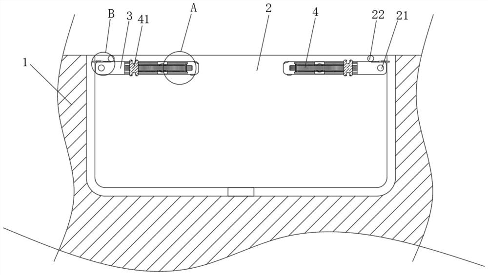
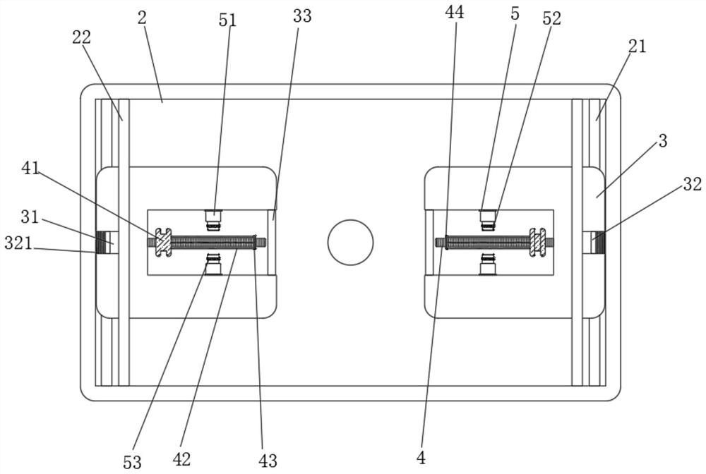
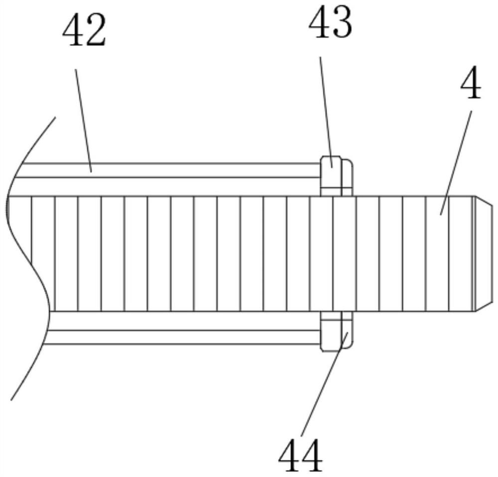
[0035] Example 1: see Figure 1-5, the multi-purpose cleaning tank of the endoscope cleaning workstation of the present invention includes a cleaning table 1, a cleaning tank 2, a connecting plate 3, a threaded rod 4 and a sliding plate 5, and the interior of the cleaning tank 2 is integrally formed with two first connecting rods 21, The connecting plate 3 is sleeved on the outside of the first connecting rod 21 , the surface of the connecting plate 3 is provided with an opening, the threaded rod 4 is fixedly connected to the surface of the connecting plate 3 , and the nuts 41 corresponding to the outside of the threaded rod 4 are located on the connecting plate 3 At the inner position of the opened opening, the front and back of the nut 41 leave space between the opening and the connecting plate 3 respectively. The nut 41 is designed with a circular structure and a limiting groove is provided along the outer side of the ring. The surface of the nut 41 is engraved with The sur...

Embodiment 2

[0036] Example 2: Unlike Example 1, see Figure 1-5 , slots 23 are provided on both sides of the inner wall of the cleaning tank 2, and a chute 31 is provided on the top surfaces of the two connecting plates 3 and at positions close to one side away from each other. The convex plate 32 in the groove 23, the top surface of the convex plate 32 runs through a plurality of grooves 321 along the horizontal longitudinal direction, and the bottom surfaces of the two connecting plates 3 and the positions close to the opposite surfaces are fixedly connected with a first rubber pad 35, When adjusting the state between the connecting plate 3 and the cleaning tank 2, the medical staff can use the groove 321 opened on the top surface of the convex plate 32 to slide the convex plate 32 inward, so that the convex plate 32 is connected to the cleaning tank. The slots 23 opened in 2 are separated, so that the connection plate 3 and the cleaning tank 2 are in a loose state, and then the connect...

Embodiment 3

[0037] Example 3: Unlike Example 1 or 2, see Figure 1-5 , the inner wall of the cleaning tank 2 is integrally formed with two limit rods 22, the surfaces of the limit rods 22 are respectively in contact with the top surfaces of the two connecting plates 3, and the surface of the connecting plate 3 is close to the opening. A fixed plate 33 is fixedly connected, and the corners of the fixed plate 33 are all designed in a smooth shape. The surface of the fixed plate 33 is set as a smooth surface. When the connecting plate 3 needs to be used, the medical staff can grasp the fixed plate 33. Press and turn over so that the top surface of the connecting plate 3 is in contact with the limiting rod 22 , and then use the convex plate 32 to limit the space between the connecting plate 3 and the cleaning tank 2 .


PUM


Abstract

The invention relates to the technical field of medical cleaning tanks, and particularly discloses a multi-purpose cleaning tank of an endoscope cleaning workstation, the multi-purpose cleaning tank comprises a cleaning table, a cleaning tank, a connecting plate, a threaded rod and a sliding plate, two first connecting rods are integrally formed in the cleaning tank, and the connecting plate sleeves the outer sides of the first connecting rods; and an opening is formed in the surface of the connecting plate. Through the position structural design of a connecting plate, a threaded rod, a nut, a second connecting rod and a first metal ring, the position adjustment of the first metal ring can be effectively utilized to achieve the clamping and limiting effect on a related electronic endoscope lens, so that the electronic endoscope lens can be stably located on the inner side of the cleaning tank, and meanwhile, the cleaning efficiency is improved. Through the structural design of a sliding plate, a spring telescopic cylinder and a limiting groove formed in the outer side of a nut, an air and water supply pipeline of the electronic lens can be effectively limited, and therefore medical workers can utilize related equipment to conduct high-pressure flushing treatment on the interior of the pipeline more easily.

Description

technical field [0001] The invention relates to the technical field of medical cleaning tanks, in particular to a multi-purpose cleaning tank for an endoscope cleaning workstation. Background technique [0002] Endoscope is a way of peeping into the deep cavity of the human body. At present, endoscopes are divided into fiber endoscopes and electronic endoscopes according to their distance from production. Fiber endoscopes are made according to the total reflection distance of optical fibers. The inner mucosal structure is sent from one end of the lumen to the outside of the body through an optical fiber, so that the doctor can observe the surface structure in the lumen. The electronic endoscope is to install a CCD (ie, charge-coupled solid glue) called a "miniature camera" at the front end of the endoscope. ), the CCD can convert the image of the intracavity structure into electrical energy and transmit it to the computer through the cable, and then the electrical signal is ...

Claims


Application Information

Patent Timeline
Patent Type & Authority Applications(China)
IPC IPC(8): A61B1/12A61B90/70B08B9/032B08B3/02B08B13/00
CPCA61B1/123A61B90/70B08B9/0321B08B3/02B08B13/00A61B2090/701
Inventor 殷晓亮殷恒才孔维群
Owner 江苏洁曼医疗科技有限公司
Why Eureka
Try Eureka