Forging and pressing piece heat treatment device

A heat treatment device and forging technology, which is applied in forging/pressing/hammer devices, heat treatment equipment, quenching devices, etc., can solve the problem that there is no way to realize the reciprocating forging of workpieces, and achieve the effect of increasing hardness

Pending Publication Date: 2022-05-27
恒利达(福建)重工发展有限公司
View PDF1 Cites 0 Cited by
  • Summary
  • Abstract
  • Description
  • Claims
  • Application Information

AI Technical Summary

Problems solved by technology

[0003] The purpose of the present invention is to provide a heat treatment device for forged parts to solve the technical problem in the prior art that there is no way to realize the reciprocating forging of the workpiece

Method used


Image

  • Forging and pressing piece heat treatment device
  • Forging and pressing piece heat treatment device
  • Forging and pressing piece heat treatment device

Examples


Embodiment 1

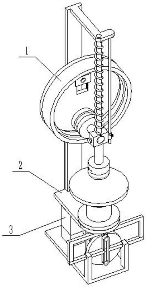
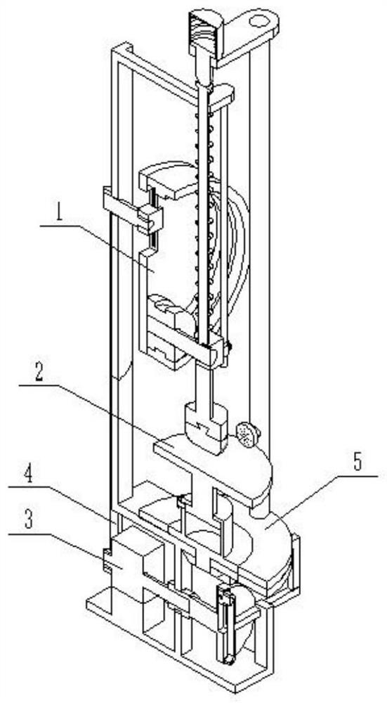
[0031] like Figure 1-12 As shown, a heat treatment device for a forging piece includes a biaxial motor 3, a driving belt 4 is connected to the biaxial motor 3, a forging assembly 1 is installed on the driving belt 4, and the lower end of the forging assembly 1 is provided with an epicyclic assembly 2, A liquid spray assembly 5 is installed on the turnover assembly 2, and this arrangement is convenient to provide driving power to the forging assembly 1 and the turnover assembly 2 through the biaxial motor 3; it is convenient to realize the forging of the workpiece through the forging assembly 1, and can be adjusted according to the actual situation. The forging range can be adjusted to adjust the forging efficiency of the workpiece; the turnover component 2 can drive the workpiece to reciprocate, so that the forging component 1 can achieve uniform forging of the workpiece; the forging component 1 drives the liquid spray component 5 during forging The gap between the parts real...

Embodiment 2

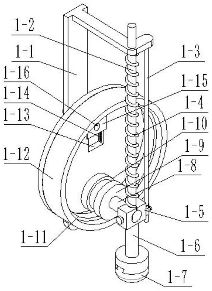
[0033] like Figure 1-12As shown, the forging assembly 1 includes a forging bracket 1-1, a connecting slide bar 1-2, an auxiliary slide bar 1-3, a spring one 1-4, a connecting block 1-5, a mounting rod 1-6, and a hammer head 1 -7. Drive rod 1-8, drive roller 1-9, annular groove 1-10, inner end convex edge 1-11, drive plate 1-12, rectangular chute 1-13, positioning slot 1- 14. Drive slider 1-15, rotating rod 1-16, positioning clamp one 1-17, positioning clamp rod push spring one 1-18, positioning screw one 1-19, positioning screw two 1-20, installation sleeve 1-21 and mounting screws 1-22, the forging bracket 1-1 is fixedly connected with the connecting slide bar 1-2, the auxiliary slide bar 1-3 is fixedly connected with the forging bracket 1-1, and the spring one 1-4 is connected with the connecting slide bar. Rods 1-2 are sleeved and connected, the connecting blocks 1-5 are fixedly connected with the connecting sliding rods 1-2, the springs 1-4 are arranged between the conne...

Embodiment 3

[0035] like Figure 1-12 As shown, the epicyclic assembly 2 includes an epicyclic support 2-1, a side wall support 2-2, a driving sliding rod 2-3, a connecting rod 2-4, a driving rack rod 2-5, a rotating sleeve 2-6, a forging Platform 2-7, lower drive plate 2-8, drive bevel 2-9, drive lever 2-10, lower rectangular chute 2-11, drive slider 2-12, matching slot 2-13, matching The clamping rod push spring 2-14, the matching clamping rod 2-15 and the locking screw 2-16, the side wall bracket 2-2 is fixedly connected with the turnover bracket 2-1, and the driving sliding rod 2-3 is connected with the side wall bracket 2 -2 sliding connection, one end of the connecting rod 2-4 is installed on the driving sliding rod 2-3, the other end of the connecting rod 2-4 is installed on the driving rack rod 2-5, the rotating sleeve 2-6 is connected with the epicyclic bracket 2 -1 Rotating connection, the forging platform 2-7 is slidingly connected with the rotating sleeve 2-6 and is positioned...


PUM


Abstract

The invention belongs to the technical field of forging and pressing piece heat treatment, and particularly relates to a forging and pressing piece heat treatment device. The technical problem that reciprocating forging of a workpiece cannot be achieved in the prior art is solved. Comprising a double-shaft motor, a driving belt is connected to the double-shaft motor, a forging and pressing assembly is installed on the driving belt, a turnover assembly is arranged at the lower end of the forging and pressing assembly, and a liquid spraying assembly is installed on the turnover assembly. Forging of the workpiece is achieved through the forging and pressing assembly, meanwhile, the forging amplitude can be adjusted according to the actual situation, and then the forging efficiency of the workpiece is adjusted. Workpieces can be driven to do turnover reciprocating motion through the turnover assembly, and then the workpieces are evenly forged through the forging and pressing assembly. The forging and pressing assembly drives the liquid spraying assembly to achieve temporary quenching of the workpiece in the gap of the forged workpiece, and then the hardness of the workpiece is improved through multiple times of machining.

Description

technical field [0001] The invention belongs to the technical field of heat treatment of forgings, and particularly relates to a heat treatment device for forgings. Background technique [0002] The patent number is CN201420670683.7 Quenching molds for heat treatment of workpieces, including upper and lower mold bodies and upper and lower water spray plates. The two spacers on the corresponding side are matched to clamp a part of the two ends of the workpiece respectively. The upper and lower mold bodies are provided with water inlet holes that communicate with the inner cavity, and each inner cavity is communicated with the corresponding water spray plate. The blocks are provided with a number of water spray holes, and the water spray holes on each cushion block are aligned and communicated with the water spray holes on the water spray plate at their corresponding positions. The bosses on the block and the water jet holes on the block are arranged staggered, but the disadv...

Claims


Application Information

Patent Timeline
Patent Type & Authority Applications(China)
IPC IPC(8): B21J7/04B21J7/32B21J13/08C21D1/667C21D1/02C21D8/00
CPCB21J7/04B21J7/32B21J13/08C21D1/667C21D1/02C21D8/00Y02P10/20
Inventor 柯志勇
Owner 恒利达(福建)重工发展有限公司
Why Eureka
Try Eureka