Convex wide die heavy blow forging (CWHF) forging method of steel ingots and convex wide anvil

A convex and wide anvil technology, applied in the field of convex wide anvils, can solve problems such as cracks on the surface of steel ingots, and achieve the effects of eliminating tensile stress, improving work efficiency and improving utilization rate.

Active Publication Date: 2021-04-16
HENAN UNIV OF SCI & TECH
View PDF6 Cites 0 Cited by
  • Summary
  • Abstract
  • Description
  • Claims
  • Application Information

AI Technical Summary

Problems solved by technology

[0005] The purpose of the present invention is to provide a steel ingot CWHF forging method to solve the technical problem that the WHF forging met

Method used


Image

  • Convex wide die heavy blow forging (CWHF) forging method of steel ingots and convex wide anvil
  • Convex wide die heavy blow forging (CWHF) forging method of steel ingots and convex wide anvil
  • Convex wide die heavy blow forging (CWHF) forging method of steel ingots and convex wide anvil

Examples


Embodiment 1

[0049] In order to make up for the shortcomings of the WHF forging method in the prior art, the present invention changes the flat wide anvil to a convex wide anvil, and invents the CWHF (Convex Wide Die Heavy Blow Forging) forging method.

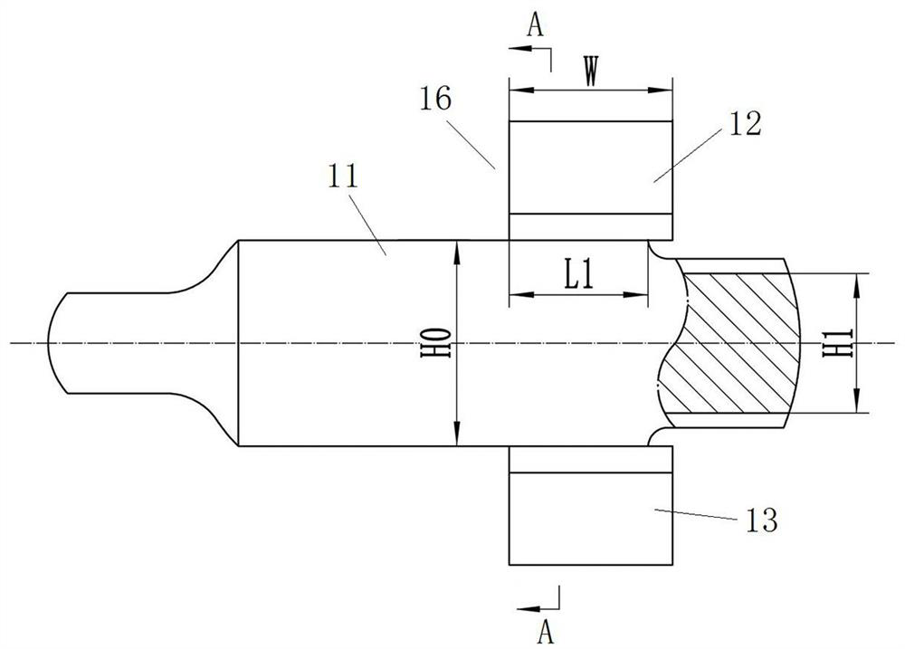
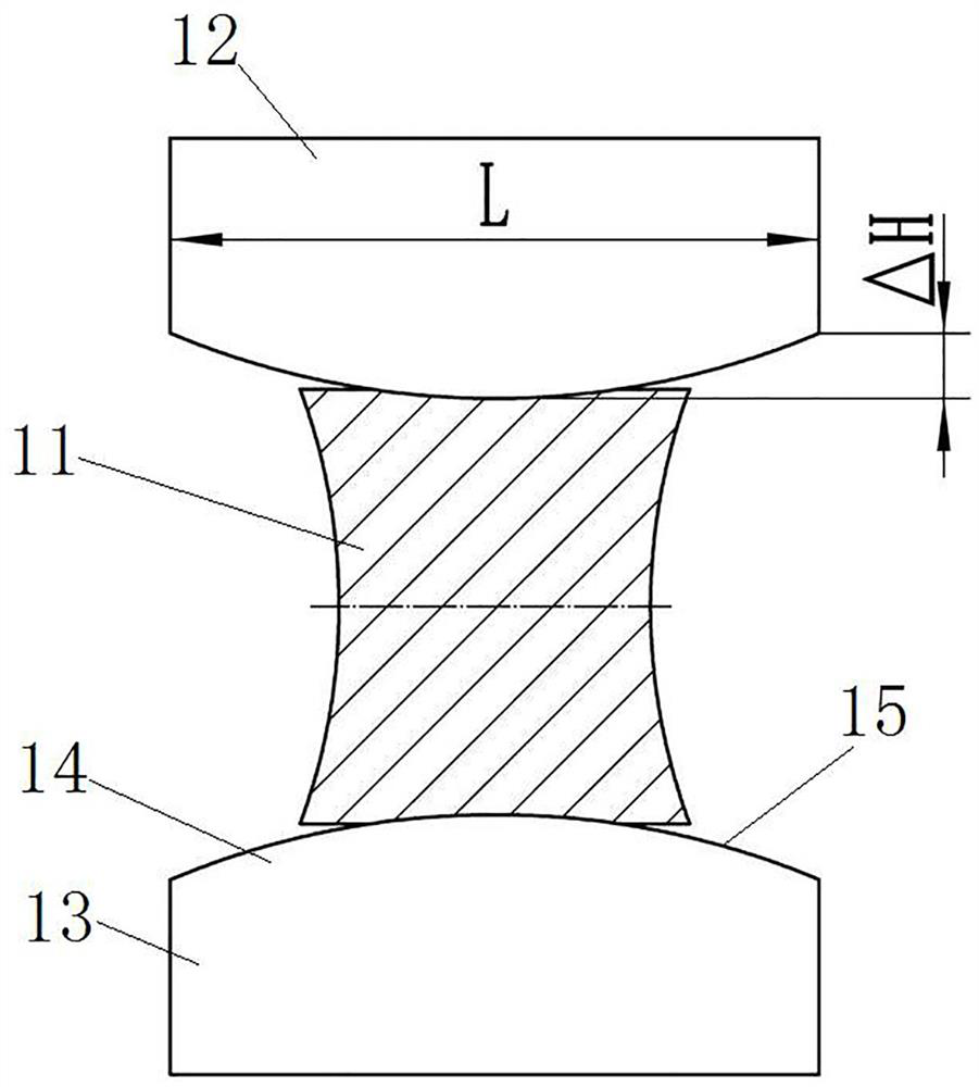
[0050] Such as figure 2 and image 3 As shown, the convex wide anvil 16 in this embodiment includes an upper anvil body 12 and a lower anvil body 13. The working surfaces of the two anvil bodies have the same shape and are spaced and symmetrically arranged in the up and down direction. When the steel ingot 11 is forged, the steel ingot 11 It is between two upper anvil bodies 12 and lower anvil bodies 13 .

[0051] The following anvil body 13 is an example, the lower anvil body 13 has a protrusion 14, and the convex surface of the protrusion 14 is the working surface 15, that is, the side of the protrusion 14 away from the lower anvil body 13 is the working surface 15, and the working surface 15 is used In the forged steel ingot 11 ; in ...

Embodiment 2

[0078] The difference between this embodiment and Embodiment 1 is that in Embodiment 1, the working surface 15 extends from one end of the lower anvil body 13 to the other end of the lower anvil body 13 in the length direction of the lower anvil body 13 . In this embodiment, due to the needs of installation, the two ends of the lower anvil body are lengthened. The actual length of the lower anvil body is greater than the length of the working surface, but it must not affect the working surface. The length and shape of the extended parts at both ends of the lower anvil body are not limited. The prerequisite is to meet the installation requirements.


PUM


Abstract

The invention relates to a convex wide die heavy blow forging (CWHF) forging method of steel ingots and a convex wide anvil. The convex wide anvil comprises an upper anvil body and a lower anvil body, wherein the upper anvil body is provided with an upper protrusion portion; the lower anvil body is provided with a lower protrusion portion; the two protrusion portions are each provided with a convex surface, and the two convex surfaces have a same shape and are oppositely arranged in the vertical direction; and the convex surfaces are working surfaces, and each working surface is an arc surface extending in the length direction of the corresponding anvil body so as to forge the steel ingots. When the steel ingots are drawn out, the upper anvil body and the lower anvil body of the convex wide anvil are used, so that the difficult-to-deform area of each steel ingot generates a certain amount of deformation, the deformation amount of the middle part is obviously increased, and the deformation of the core part of each steel ingot is further enhanced, thus being conducive to eliminating the defects of the core defects; and moreover, a concave surface is formed on each of the upper and lower surfaces of each steel ingot, and after each steel ingot is overturned 90 degrees, the side surface of the steel ingot is the concave surface, and thus, protrusions generated when the side surfaces are broadened can be greatly reduced or even eliminated, and then, the tensile stress in the protrusions is reduced or even eliminated, so that the initiation and propagation of cracks are effectively inhibited, the utilization rate of the steel ingots is improved, waste is avoided, and meanwhile, the working efficiency is improved.

Description

technical field [0001] The invention relates to a steel ingot CWHF forging method and a convex wide anvil. Background technique [0002] There are a large number of defects such as shrinkage cavities, porosity, inclusions, and segregation inside large steel ingots, and these defects need to be eliminated in the subsequent forging process. Among them, the WHF forging method is a wide anvil strong reduction forging method. The WHF method uses upper and lower wide flat anvils and a large reduction rate. The ratio should reach 0.68-0.77, and the reduction rate should be at least 20% each time. The above method mainly focuses on the large deformation of the core of the steel ingot. The deformation of the core is much larger than that of ordinary flat anvils, which is very beneficial to eliminate defects such as shrinkage cavity and looseness inside the steel ingot. At the same time, due to the symmetrical deformation of the billet by the WHF method and easy operation, it is esp...

Claims


Application Information

Patent Timeline
IPC IPC(8): B21J13/06B21J13/08
Inventor 周玉成魏世忠徐流杰熊美毛丰陈冲李秀青
Owner HENAN UNIV OF SCI & TECH
Why Eureka
Try Eureka