A three-direction precision compensation structure of xyz axis suitable for precision handling mechanism

A handling mechanism and precision compensation technology, applied in metal processing machinery parts, metal processing equipment, manufacturing tools, etc., can solve the problems of affecting the structural accuracy and strength, vacuum leakage, and high cost, and improve the handling success rate and relative position accuracy. , Compensate the effect of machining accuracy

Active Publication Date: 2022-07-15
沈阳和研科技股份有限公司
View PDF0 Cites 0 Cited by
  • Summary
  • Abstract
  • Description
  • Claims
  • Application Information

AI Technical Summary

Problems solved by technology

[0002] The handling mechanism of the precision CNC machining machine tool controls the handling action through its own X-axis, Y-axis, and Z-axis. The X-axis, Y-axis, and Z-axis determine the handling accuracy of the handling mechanism; The cutting disc is transported to the cleaning module, and then to the turning and drying module. During the cutting process, a whole piece of semi-finished product will be cut into several small semi-finished products. The suction cups of the hole respectively suck each small semi-finished workpiece to be transported to the next processing module; the side length of the workpiece transported by the transport mechanism is as small as about 2mm, and the diameter of the suction hole of the suction cup used for transportation is already close to the minimum workpiece side length. The handling position is abnormal, the position of the suction cup and the workpiece is deviated, and the vacuum is likely to leak in the misaligned suction hole, which will cause poor handling, affect the structural accuracy and strength, and even fail to transport; The solution to the problem of handling accuracy is to use high-precision screw to cooperate with the X-axis, Y-axis, and Z-axis of the handling mechanism. This method does not improve the accuracy well, and the cost is too high

Method used


Image

  • A three-direction precision compensation structure of xyz axis suitable for precision handling mechanism
  • A three-direction precision compensation structure of xyz axis suitable for precision handling mechanism
  • A three-direction precision compensation structure of xyz axis suitable for precision handling mechanism

Examples


Embodiment Construction

[0027] In order to make the technical problems, technical solutions and beneficial effects solved by the present invention clearer, the present invention will be further described in detail below with reference to the accompanying drawings and specific embodiments. It should be understood that the specific embodiments described herein are only used to explain the present invention, but not to limit the present invention.

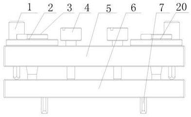
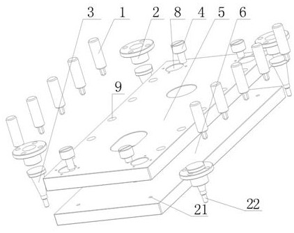
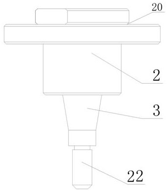
[0028] like figure 1 and figure 2 As shown, an XYZ axis three-direction precision compensation structure suitable for a precision handling mechanism of the present invention includes a mechanism upper mounting plate 5 , a mechanism lower mounting plate 6 , a guide assembly 20 , an elastic plunger 1 , and a top tightening screw 4 .

[0029] The upper mounting plate 5 of the mechanism is arranged in parallel with the lower mounting plate 6 of the mechanism, and the upper mounting plate 5 of the mechanism is provided with a guide assembly 20 and an elastic pl...


PUM


Abstract

The invention discloses an XYZ axis three-direction precision compensation structure suitable for a precision handling mechanism, comprising an upper mounting plate and a lower mounting plate of the mechanism, a guide component and an elastic plunger are arranged on the upper mounting plate of the mechanism; the guide component is arranged on the mechanism At the four corners of the installation plate, elastic plungers are arranged symmetrically on the opposite edges of the upper installation plate of the mechanism, the bottom of the elastic plunger is connected to the lower installation plate of the mechanism, and the guide assembly is inserted into the lower installation plate of the mechanism; the guide assembly includes Guide sleeve and guide shaft, the guide sleeve is fixed on the upper installation plate of the mechanism, the guide shaft is in the guide sleeve and the bottom of the guide shaft is inserted into the lower installation plate of the mechanism, and is squeezed to the elastic plunger by the downward movement of the Z axis of the conveying mechanism The guide shaft and the guide sleeve can be separated, and a matching gap is formed between the separated guide shaft and the guide sleeve; the upper mounting plate of the mechanism is also provided with a top tightening screw. The invention realizes the three-direction precision compensation of the XYZ axis of the transport mechanism, and improves the transport success rate, the transport precision and the transport quality.

Description

technical field [0001] The invention belongs to the technical field of precision machine tool equipment components, and in particular relates to an XYZ axis three-direction precision compensation structure suitable for a precision handling mechanism. Background technique [0002] The handling mechanism of the precision CNC machine tool equipment controls the handling action through its own X-axis, Y-axis, and Z-axis. The X-axis, Y-axis, and Z-axis determine the handling accuracy of the handling mechanism; The cutting disc is transported to the cleaning module, and then transported to the turning drying module. The cutting process will cut a whole semi-finished product into several small semi-finished products. The suction cup of the hole sucks each small semi-finished workpiece and transports it to the next processing module; the side length of the workpiece handled by the handling mechanism is as small as about 2mm, and the diameter of the suction hole of the suction cup us...

Claims


Application Information

Patent Timeline
Patent Type & Authority Patents(China)
IPC IPC(8): B23Q1/25
CPCB23Q1/25
Inventor 张明明袁慧珠杨盛刘苏阳石文徐双双
Owner 沈阳和研科技股份有限公司
Why Eureka
Try Eureka