
Numerical control device machining lathe for graphite tower section

A technology of lathe and graphite, which is applied in the field of machining lathes with numerical control devices for graphite tower joints. It can solve the problems of unable to collect and process dust particles, unable to reduce the interference of the manufacturing quality of graphite tower joints of lathes, and normal use of processing lathes.

Active Publication Date: 2022-05-27
南通凌睿自动化科技有限公司
View PDF18 Cites 0 Cited by
  • Summary
  • Abstract
  • Description
  • Claims
  • Application Information

AI Technical Summary

Problems solved by technology

[0004] Aiming at the deficiencies in the prior art, the present invention provides a graphite tower section CNC device processing lathe, which solves the problem that the processing lathe cannot be used normally in a relatively humid environment and cannot reduce the impact of water vapor and dust around the lathe on the graphite tower section manufacturing quality. Interference, the problem that the dust particles generated during the processing cannot be effectively collected and processed

Method used


Image

  • Numerical control device machining lathe for graphite tower section
  • Numerical control device machining lathe for graphite tower section
  • Numerical control device machining lathe for graphite tower section

Examples


Embodiment 1

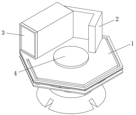
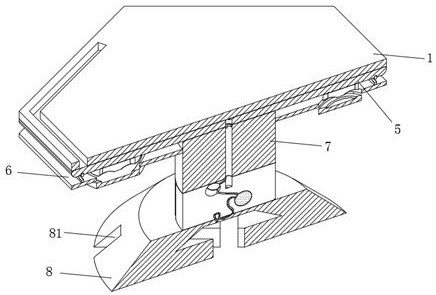
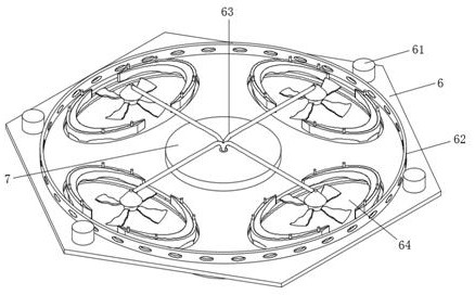
[0030] see Figure 1-7 , The present invention provides a technical solution: a CNC device processing lathe for graphite tower sections, including a lathe top plate 1, the top of the lathe top plate 1 is installed with a processing component 2 for processing the graphite tower section, and the top of the lathe top plate 1 is installed. In order to control the numerical control mechanism 3 of the lathe, the top middle of the top plate 1 of the lathe is installed with a fixed platform 4 for fixing the graphite tower section, the lower end of the lathe top plate 1 is installed with a No. The middle part of the lower end of the number plate 5 is connected to the column foot 7 through the second plate 6. The inner part of the column foot 7 is provided with a guide cavity 71. The lower end of the column foot 7 is connected with a storage body 72 for storing dust and water vapor. The bottom end of the column foot 7 A horseshoe table 8 is installed, and the bottom surface of the horse...

Embodiment 2

[0036] like Figure 1-7 As shown, the present invention provides a technical solution: a CNC device processing lathe for graphite tower sections, comprising a lathe top plate 1, the top of the lathe top plate 1 is installed with a processing component 2 for processing the graphite tower section, and the top of the lathe top plate 1 is installed. A numerical control mechanism 3 for controlling the lathe is installed, a fixed platform 4 for fixing the graphite tower section is installed in the top middle of the top plate 1 of the lathe, a No. , the middle part of the lower end of the first plate 5 is connected with the column foot 7 through the second plate 6, the inner part of the column foot 7 is provided with a guide cavity 71, and the lower end of the column foot 7 is connected with a storage body 72 for storing dust and water vapor. The bottom end is provided with a horseshoe table 8, and the bottom surface of the horseshoe table 8 is provided with a cross cavity groove 81 ...


PUM


Abstract

The numerical control device machining lathe for the graphite tower section comprises a lathe top plate, a machining assembly used for machining the graphite tower section is installed at the top end of the lathe top plate, and a numerical control mechanism used for controlling the lathe is installed at the top end of the lathe top plate. A fixing table for fixing a graphite tower section is mounted in the middle of the top end of the lathe top plate; the invention relates to the technical field of graphite processing. According to the machining lathe, a gap between the second plate and the first plate can be isolated through an annular cover net installed at the top end of the second plate and a bottom protective cover installed at the bottom end of the second plate and an arc plate in a corresponding buckled mode, air circulation is achieved, meanwhile, foreign matter can be effectively blocked outside, and the machining efficiency is improved. Foreign matters are prevented from entering the device to interfere with normal operation of the air return fan.

Description

technical field [0001] The invention relates to the technical field of graphite processing, in particular to a numerical control device processing lathe for graphite tower sections. Background technique [0002] Graphite tower is a tower equipment used for gas-liquid or liquid-liquid mass transfer made of graphite material. The capacity and inner diameter are small; when the inner diameter exceeds 100mm or the inner pressure exceeds 0.2MPa, it is often reinforced with metal materials; according to the structure, graphite towers can be divided into two categories: packed towers and plate towers; [0003] The processing lathes on the market cannot be used normally in a relatively humid environment, cannot reduce the interference of water vapor and dust around the lathe on the manufacturing quality of the graphite tower section, and cannot effectively collect and process the dust particles generated during processing. For this reason, we A numerical control device processing l...

Claims


Application Information

Patent Timeline
Patent Type & Authority Applications(China)
IPC IPC(8): B28D1/16B28D7/02B28D7/00
CPCB28D1/16B28D7/02B28D7/00Y02P70/10
Inventor 姚松年
Owner 南通凌睿自动化科技有限公司
Learn More