Oil film thickness measuring method based on real part of ultrasonic reflection coefficient

A technology of reflection coefficient and oil film thickness, which is applied in the re-radiation of sound waves, radio wave measurement systems, and the use of ultrasonic/sonic/infrasonic waves, etc., to achieve high measurement accuracy and important engineering application value

Pending Publication Date: 2022-05-27
HARBIN INST OF TECH +1
View PDF0 Cites 2 Cited by
  • Summary
  • Abstract
  • Description
  • Claims
  • Application Information

AI Technical Summary

Problems solved by technology

[0006] Aiming at the upper limit problem of oil film thickness measurement in the existing ultrasonic reflection coefficient amplitude method, the present invention provides an oil film thickness measurement method based on the real part of ultrasonic reflection coefficient

Method used


Image

  • Oil film thickness measuring method based on real part of ultrasonic reflection coefficient
  • Oil film thickness measuring method based on real part of ultrasonic reflection coefficient
  • Oil film thickness measuring method based on real part of ultrasonic reflection coefficient

Examples


specific Embodiment approach 1

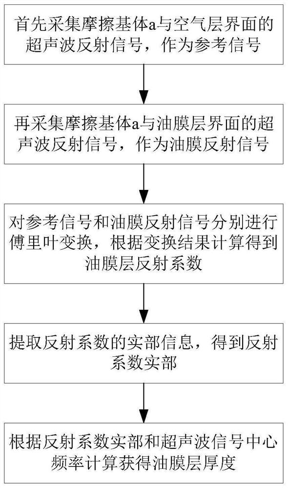
[0040] Specific implementation mode 1. Combination figure 1 and image 3 As shown, the present invention provides a method for measuring oil film thickness based on the real part of the ultrasonic reflection coefficient, comprising:

[0041] The ultrasonic transducer is arranged on the upper surface of the friction substrate a; the pulse transceiver is used to send out periodic pulses to excite the ultrasonic transducer, so that the ultrasonic transducer sends out an ultrasonic signal with a preset width;

[0042] Firstly, the gap between the friction substrate a and the friction substrate b is an air layer, and the ultrasonic reflection signal of the interface between the friction substrate a and the air layer is collected as the reference signal required for calculating the reflection coefficient;

[0043] Then add lubricating oil between the friction substrate a and the friction substrate b to form an oil film layer, and collect the ultrasonic reflection signal at the inte...

specific Embodiment

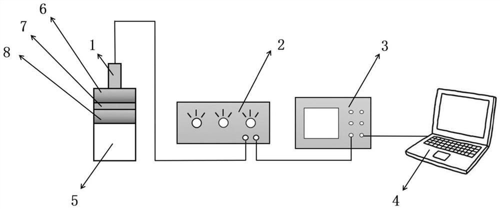
[0067] build as image 3 The shown experimental platform for oil film thickness calibration and ultrasonic measurement is used to verify the effectiveness of the method of the present invention. Periodic pulses are sent out by the pulse transceiver 2. After the ultrasonic transducer 1 is excited, an ultrasonic signal is sent out. The ultrasonic signal passes through the substrate a and is emitted at the substrate a-air interface. The reflected signal returns along the original path and is sent to the data acquisition card 3. A recording is made as a reference signal required to calculate the oil film thickness. After the reference signal is measured, a certain amount of lubricating oil is added between the substrate a and the substrate b to form a lubricating oil film. The thickness of the lubricating oil film is changed by the macro-micro composite displacement stage 5, and the reflected signal of the oil film layer is recorded by the data acquisition card 3. Use the comput...


PUM

PropertyMeasurementUnit
thicknessaaaaaaaaaa

Abstract

The invention discloses an oil film thickness measuring method based on an ultrasonic reflection coefficient real part, and belongs to the field of lubricating state ultrasonic monitoring. The method aims at solving the problem of oil film thickness measurement upper limit of an existing ultrasonic reflection coefficient amplitude method. Firstly, a gap between a friction matrix a and a friction matrix b is an air layer, and ultrasonic reflection signals of an interface between the friction matrix a and the air layer are collected to serve as reference signals; then adding lubricating oil between the friction matrix a and the friction matrix b to form an oil film layer, and collecting an ultrasonic reflection signal of an interface between the friction matrix a and the oil film layer as an oil film reflection signal; respectively carrying out Fourier transform on the reference signal and the oil film reflection signal, and calculating to obtain an oil film layer reflection coefficient; extracting real part information of the reflection coefficient to obtain a reflection coefficient real part; and calculating the thickness of the oil film layer according to the real part of the reflection coefficient and the ultrasonic signal center frequency. According to the method, the upper limit of oil film thickness measurement can be improved by tens of microns, and higher oil film thickness measurement precision is realized.

Description

technical field [0001] The invention relates to a method for measuring oil film thickness based on the real part of ultrasonic reflection coefficient, and belongs to the field of ultrasonic monitoring of lubrication state. Background technique [0002] In mechanical equipment, the lubricating oil film formed between the friction surfaces is the key factor to reduce friction and wear and ensure the stable operation of the equipment. When the thickness of the oil film is too small, the oil film will rupture at the place where the impact is large, and the friction pair will be in a state of dry friction, which will cause the temperature of the contact surface to increase and the friction and wear to increase. , and will cause unnecessary energy loss. Therefore, real-time monitoring of changes in oil film thickness is crucial to ensuring the stable operation of the equipment and improving the mechanical efficiency of the equipment. [0003] Oil film thickness measurement metho...

Claims


Application Information

Patent Timeline
Patent Type & Authority Applications(China)
IPC IPC(8): G01B17/02G01S15/02
CPCG01B17/025G01S15/02
Inventor 古乐贺彦博汪剑云张传伟王黎钦李宛蓉汤华
Owner HARBIN INST OF TECH
Why Eureka
Try Eureka