
Rotary anti-electric shock switch

An anti-shock switch, rotary technology, applied in electrical switches, circuits, electrical components, etc., can solve the problems of poor safety, the conductive moving contacts cannot be isolated, and the structure is unreasonable, and achieve the effect of preventing damage.

Inactive Publication Date: 2022-05-27
侯丹洁
View PDF0 Cites 0 Cited by
  • Summary
  • Abstract
  • Description
  • Claims
  • Application Information

AI Technical Summary

Problems solved by technology

When not in use, first rotate the conductive movable contact to separate the conductive movable contact from the conductive fixed contact, and then rotate the insulating partition plate to separate the conductive movable contact from the conductive fixed contact by the shielding protrusion. It can be seen that, When not in use, if the operator forgets to rotate the insulating partition, the conductive contact cannot be isolated. At this time, when an external conductive foreign object (such as a finger) is inserted into the groove-shaped cavity, the conductive foreign object may replace the conductive contact. The electric contact and the conductive fixed contact can still realize the conduction of the circuit, so that the insulating partition plate loses the anti-shock effect, and the conductive foreign matter still has the risk of electric shock to the human body. Therefore, the existing rotary anti-shock switch The structure is unreasonable, there is still a risk of electric shock, and the safety is poor

Method used


Image

  • Rotary anti-electric shock switch
  • Rotary anti-electric shock switch
  • Rotary anti-electric shock switch

Examples


Embodiment Construction

[0019] In order to make the purpose and advantages of the present invention more clearly understood, the present invention will be described in detail below in conjunction with the examples. It should be understood that the following words are only used to describe one or several specific embodiments of the present invention, and do not specifically request the present invention. The scope of protection is strictly limited, and as used herein, the terms up-down and left-right are not limited to their strict geometric definitions, but include reasonable and inconsistency tolerances for machining or human error, a rotation that is described in detail below. The specific characteristics of the anti-shock switch:

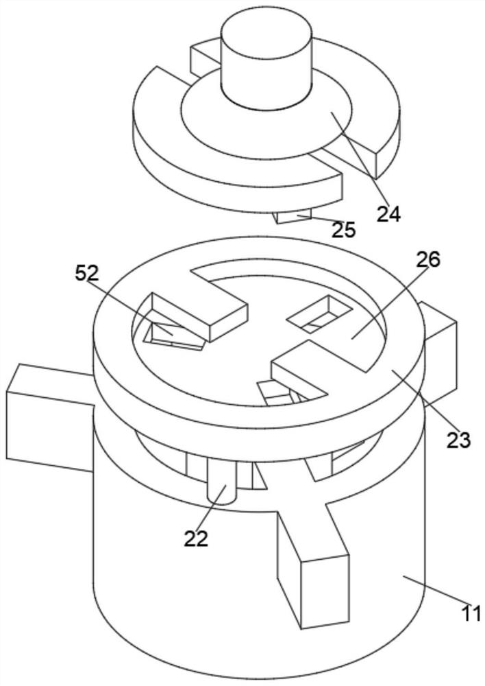
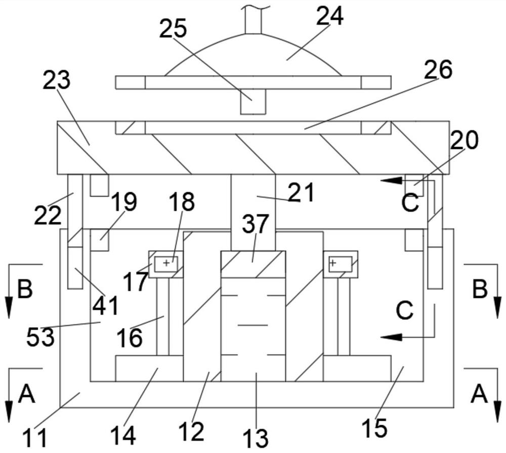
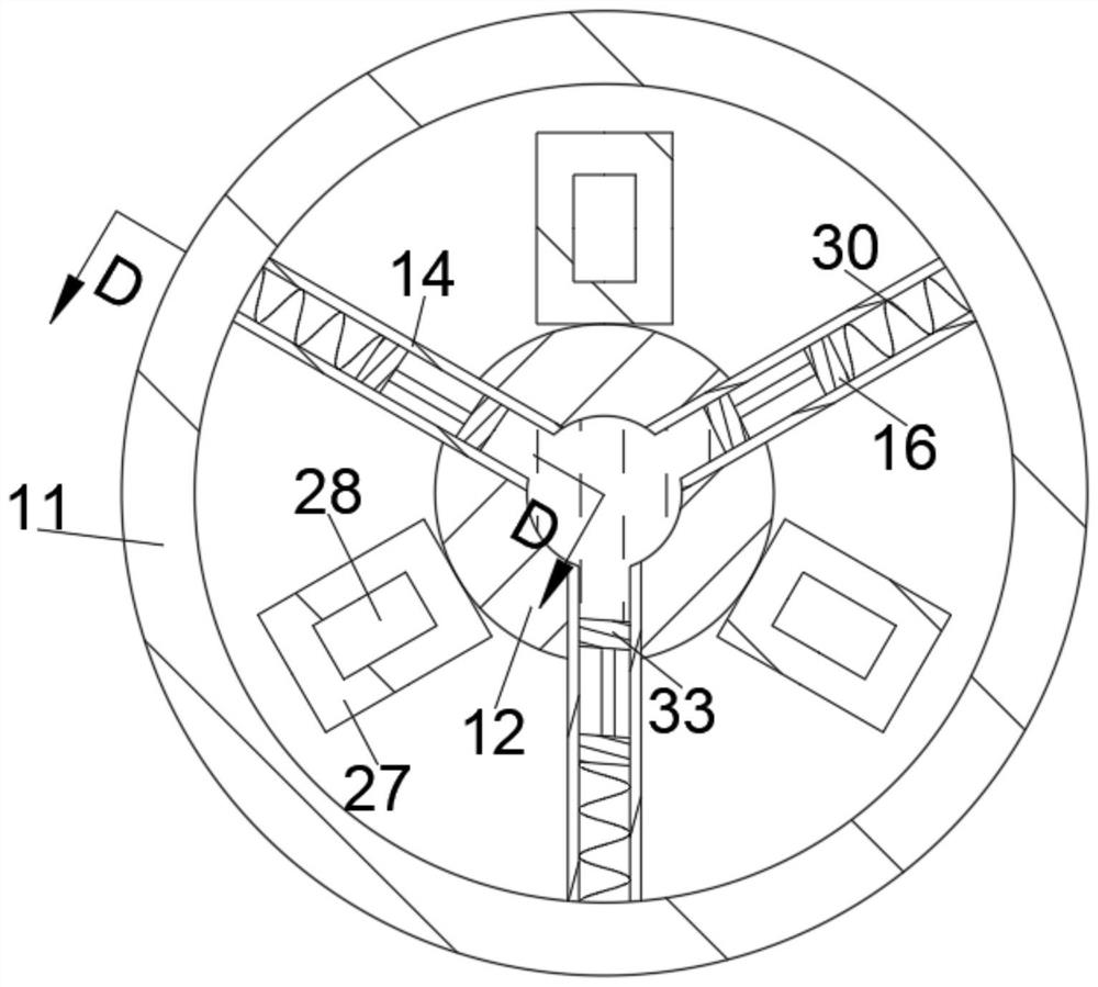
[0020] Refer to the attached Figure 1-Figure 6 , according to an embodiment of the present invention, a rotary anti-shock switch includes an insulating base 11, a working cavity 15 is opened in the insulating base 11, and a protective mechanism 53 is arranged in the wo...


PUM


Abstract

A rotary anti-electric-shock switch comprises an insulating base, a working cavity is formed in the insulating base, a protection mechanism is arranged in the working cavity, the protection mechanism is used for separating power supply pieces, the protection mechanism comprises a fixing column fixedly arranged on the bottom wall of the working cavity, a hydraulic cavity is formed in the fixing column, and the hydraulic cavity is provided with a hydraulic cylinder. According to the invention, through the arrangement of the protection mechanism, an insulating plate can be automatically popped up to block a power supply sheet when the device is not used, a first protection effect is achieved, meanwhile, a height difference exists between a limiting disc and an insulating socket by using a rotating rod, a second protection effect is started, and the safety of the device is improved. And the insulating plate can be shrunk only by rotating the limiting disc and then pressing the limiting disc downwards, so that a second protection effect is achieved, and damage to a human body caused by circuit connection due to carelessness is prevented.

Description

technical field [0001] The invention relates to the technical field of electrical components, in particular to a rotary electric shock-proof switch. Background technique [0002] Existing rotary anti-shock switches usually include sockets, plugs, and insulating dividers. The center of the socket is provided with a groove-shaped cavity, and a plurality of conductive fixed contacts arranged in a ring are evenly distributed in the groove-shaped cavity. The bottom of the plug is provided with a circular truncated body for supporting a plurality of conductive moving contacts, and the circular truncated body is matched with the groove-shaped cavity. The insulating partition plate is arranged between the socket and the plug, and is provided with a plurality of shielding protrusions for shielding the conductive fixed contacts. When in use, insert the circular truncated body into the groove-shaped cavity, and then rotate the insulating baffle to make the shielding protrusion avoid ...

Claims


Application Information

Patent Timeline
Patent Type & Authority Applications(China)
IPC IPC(8): H01H19/02H01H19/08H01H19/10H01R24/00
CPCH01H19/02H01H19/08H01H19/10H01R24/00
Inventor 侯丹洁
Owner 侯丹洁
Learn More