Novel lithium battery with positive electrode and negative electrode capable of being automatically powered off
A self-power-off, positive and negative technology, applied in the field of new lithium batteries, can solve the problems of inability to automatically power off, chemical reaction is not fast enough, easy to damage and so on
- Summary
- Abstract
- Description
- Claims
- Application Information
AI Technical Summary
Problems solved by technology
Method used
Image

Examples
Embodiment 1
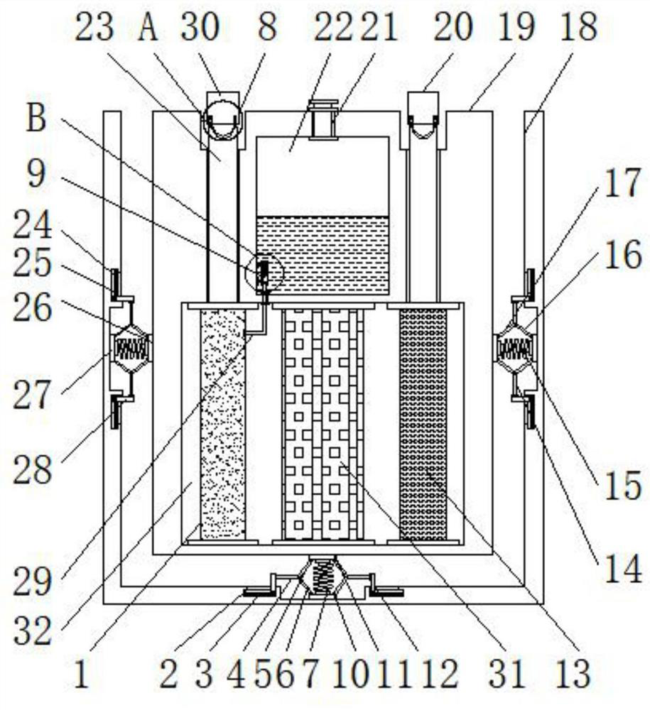
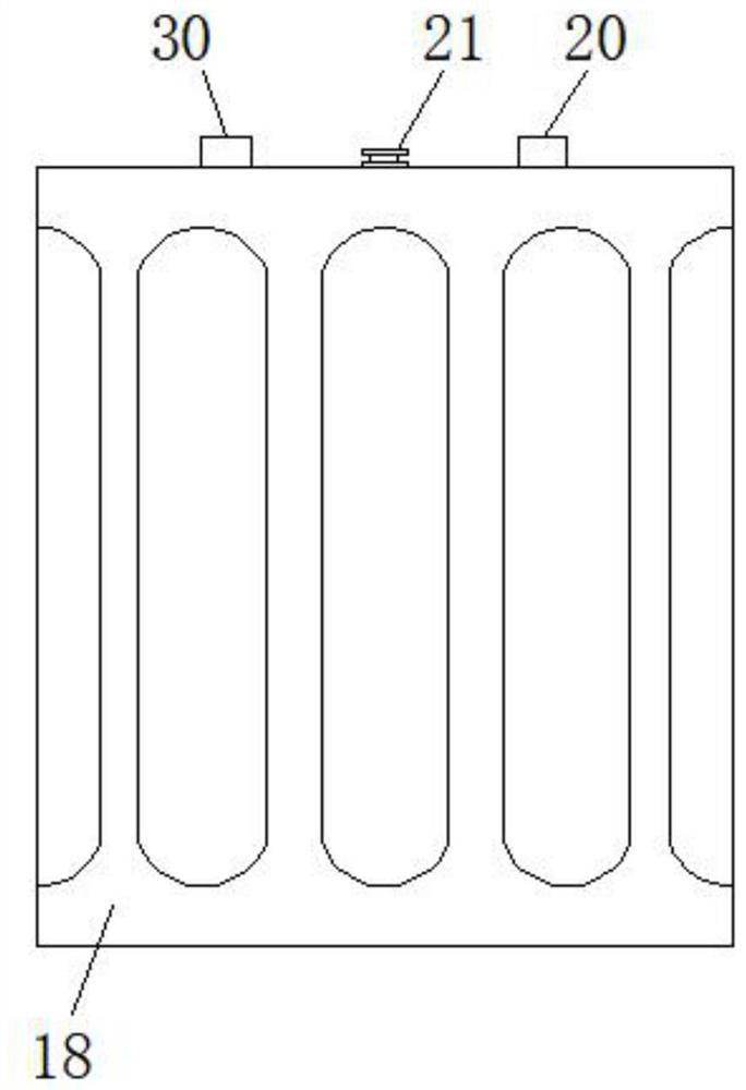
[0025] Example 1: see Figure 1-4 , a new type of lithium battery with self-power-off of positive and negative electrodes, including a casing 18 and a main body 19, a shock-absorbing structure to prevent impact damage, a telescopic structure 8 for automatic power-off, and a closed structure 9 for controlling the addition of catalysts;
[0026] A main body 19 is provided inside the housing 18 , a fifth cavity 32 is opened at the bottom end of the main body 19 , and an electrolyte membrane plate 31 is installed vertically inside the fifth cavity 32 . The electrolyte membrane inside the fifth cavity 32 The positive electrode plate 1 is installed vertically on one side of the plate 31, and the negative electrode plate 13 is installed vertically on the other side of the electrolyte diaphragm plate 31 inside the fifth cavity 32. The tops of the positive electrode plate 1 and the negative electrode plate 13 are installed with conductive columns 23 , and the tops of the conduction col...
Embodiment 2
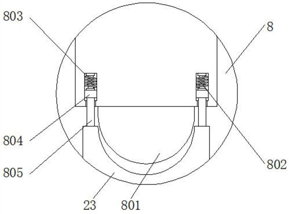
[0031] Embodiment 2: The telescopic structure 8 includes a contact block 801 , a reciprocating spring 802 , a second cavity 803 , a first slider 804 and a fixing rod 805 , and the first slider 804 is opened inside the bottom end of the negative electrode sheet 20 and the positive electrode sheet 30 On both sides of the second cavity 803, reciprocating springs 802 are installed at the top of the second cavity 803, first sliders 804 are installed in the second cavity 803 through the reciprocating springs 802, and the bottom ends of the first sliders 804 are installed There are fixed rods 805, the bottom ends of the fixed rods 805 extend to both sides of the top of the conductive column 23, and the contact blocks 801 are installed on the bottom ends of the negative electrode sheet 20 and the positive electrode sheet 30;
[0032] Specifically, as image 3 As shown in the figure, when using this mechanism, the facilities that need to be powered are connected to the negative electro...
Embodiment 3
[0033] Embodiment 3: The closed structure 9 includes a second slider 901, a plug rod 902, a third cavity 903, an electromagnet 904 and a cavity plate 905. The cavity plate 905 is installed at the bottom end of one side inside the liquid storage cavity 22, And a third cavity 903 is opened in the cavity plate 905, an electromagnet 904 is installed at the top of the third cavity 903, and a second slider 901 is disposed below the electromagnet 904 in the third cavity 903;
[0034] A plug rod 902 is mounted on the bottom end of the second sliding block 901, and the bottom end of the plug rod 902 extends to the top of the liquid injection pipe 29;
[0035] Specifically, as Figure 4 As shown in the figure, when using this mechanism, during the reaction process, if the amount of electricity generated is not obvious or small, the catalyst can be injected into the liquid storage chamber 22 through the liquid injection port 21, and when electrification occurs, it is installed on the cav...
PUM
 Abstract
Description
Claims
Application Information
 - R&D
- Intellectual Property
- Life Sciences
- Materials
- Tech Scout
- Unparalleled Data Quality
- Higher Quality Content
- 60% Fewer Hallucinations
Browse by: Latest US Patents, China's latest patents, Technical Efficacy Thesaurus, Application Domain, Technology Topic, Popular Technical Reports.
© 2025 PatSnap. All rights reserved.Legal|Privacy policy|Modern Slavery Act Transparency Statement|Sitemap|About US| Contact US: help@patsnap.com