Convenient-to-move sewage disposal equipment for water conservancy project drainage station
A water conservancy project and decontamination technology, which is applied in the direction of water conservancy engineering equipment, water conservancy projects, cleaning hollow objects, etc., can solve the problems that the separation pipe does not have the decontamination function and affects the normal transportation of the separation leaves, and achieves the effect of convenient decontamination
- Summary
- Abstract
- Description
- Claims
- Application Information
AI Technical Summary
Problems solved by technology
Method used
Image
Examples
Embodiment 1
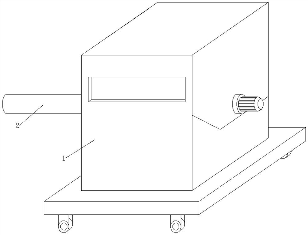
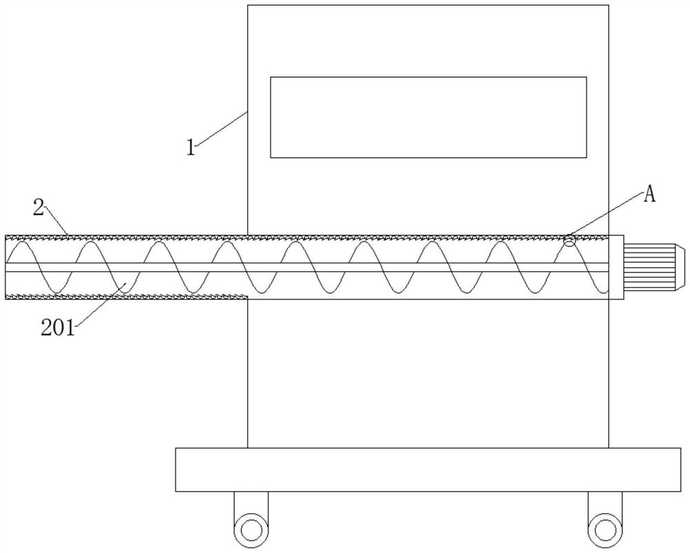
[0034] see Figure 1-3 , in an embodiment of the present invention, a water conservancy project drainage station that is easy to move, includes a cleaning main body 1, a separation pipe 2 and a separation leaf 201, and the inner wall of the separation pipe 2 is arranged in an equi-adjacent manner to encircle and insert Several decontamination components 3 that can remove the sticky sludge block;
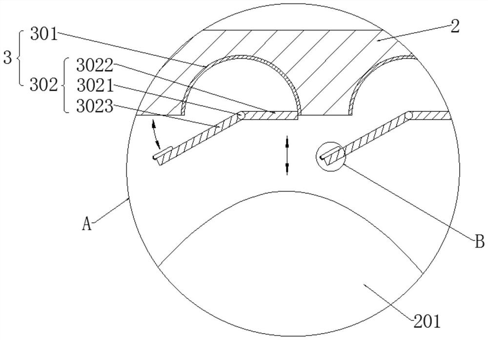
[0035] Each group of decontamination components 3 includes a spherical shell 301 and a movable component 302 that can move flexibly according to the approach of the separating leaves 201 .
[0036] In the embodiment of the present invention, the appearance of each spherical shell 301 is in the shape of a hollow hemisphere, and each spherical shell 301 is embedded in the inner wall of the separation tube 2, and the inner bottom of each spherical shell 301 is The activity is installed with the activity component 302;
[0037] The outer appearance of the spherical shell 301 is in the ...
Embodiment 2
[0040] see image 3 Compared with Embodiment 1, this embodiment of the present invention differs in that each set of movable components 302 includes a rotating rod 3021 , a right rotating plate 3022 and a left rotating plate 3023 .
[0041] In the embodiment of the present invention, each rotating rod 3021 is installed in the middle of the bottom end of the inner wall of each spherical shell 301 in a forward and backward horizontal direction, and the right and left outer surfaces of each rotating rod 3021 are respectively fixedly installed with Right turning plate 3022 and left turning plate 3023;
[0042] The right turning plate 3022 and the left turning plate 3023 here are to utilize the principle of leverage to remove the sludge block.
[0043] In the embodiment of the present invention, the length of each left rotating plate 3023 is greater than the length of each right rotating plate 3022;
[0044] Here, the length of the left rotating plate 3023 is set to be greater th...
Embodiment 3
[0055] see Figure 4 and Figure 5 Compared with Embodiment 1, the embodiment of the present invention differs in that an airbag 30231 is fixedly installed on the left end of the top outer surface of each left rotating plate 3023, and an airbag 30231 is fixedly installed on the left outer surface of each airbag 30231. There are arc plates 30232, and a plurality of steel needles 30233 are fixedly arranged on the left outer surface of each arc plate 30232 in equal rows;
[0056] The air bag 30231 here is to use the principle of negative pressure to squeeze the left rotating plate 3023 every time it touches the inner wall of the separation pipe 2 to remove the nearby sludge blocks; and the arc plate 30232 is to prevent the air bag 30231 from When the steel needle 30233 hits the sludge block, the air bag 30231 is inserted back inward to cause a puncture; the several settings of the steel needle 30233 are to achieve the effect of brushing the sludge block, and the hardness of the ...
PUM
 Abstract
Description
Claims
Application Information
 - R&D
- Intellectual Property
- Life Sciences
- Materials
- Tech Scout
- Unparalleled Data Quality
- Higher Quality Content
- 60% Fewer Hallucinations
Browse by: Latest US Patents, China's latest patents, Technical Efficacy Thesaurus, Application Domain, Technology Topic, Popular Technical Reports.
© 2025 PatSnap. All rights reserved.Legal|Privacy policy|Modern Slavery Act Transparency Statement|Sitemap|About US| Contact US: help@patsnap.com


