Plate hole reaming conveying device for copper pipe

A conveying device and plate technology, applied in the field of conveying, can solve problems such as troublesome operation, and achieve the effect of improving the pass rate and accuracy

Active Publication Date: 2022-07-19
常州九洲创胜特种铜业有限公司
View PDF12 Cites 0 Cited by
  • Summary
  • Abstract
  • Description
  • Claims
  • Application Information

AI Technical Summary

Problems solved by technology

[0003] The hole reaming machine in the prior art, when reaming the plate, generally adopts the method of manually pushing in, reaming it, visually locating the position of the hole, and then fixing the plate, after each time the hole is reamed It needs to be unfixed, and then fix the next positioning hole, which is very troublesome to operate

Method used


Image

  • Plate hole reaming conveying device for copper pipe
  • Plate hole reaming conveying device for copper pipe
  • Plate hole reaming conveying device for copper pipe

Examples


Embodiment 1

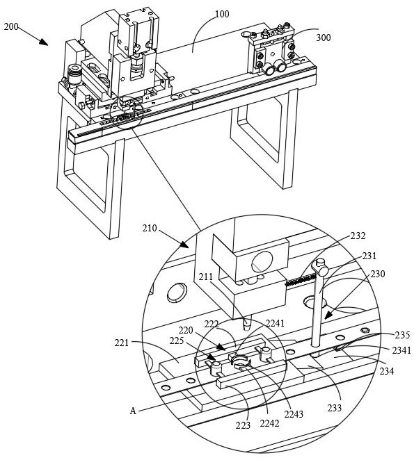
[0079] see Figure 1-Figure 5 , this embodiment 1 provides a plate hole reaming and conveying device for copper pipes, including: a workbench 100 and a hole expansion mechanism 200; the hole expansion mechanism 200 is arranged on the workbench 100 and is suitable for the plate Equally spaced reaming; the reaming mechanism 200 includes a reaming component 210, a reaming base 220 and a pushing component 230; the reaming base 220 is arranged on the worktable 100; the reaming component 210 is arranged on the The reaming base 220 is above the reaming base 220 and is suitable for reaming the plate on the reaming base 220; the pushing component 230 is disposed at the discharge end of the reaming base 220 and is suitable for expanding the plate Push the end of the hole back.

[0080] Specifically, the pusher assembly 230 includes a push rod 231, a return spring 232 and an oblique slider 233; the oblique slider 233 is fixedly arranged on the discharge side of the reaming base 220; the...


PUM


Abstract

The invention belongs to the field of conveying, and in particular relates to a plate hole reaming conveying device for copper pipes, which realizes automatic material pushing by arranging a pushing component; It is the same as the distance between the two adjacent positioning holes in the plate; by setting the oil storage bin, after the push rod is inserted into the oil storage bin each time, when the push rod is pulled out, the through hole after the reaming can be carried out. Lubricant application.

Description

technical field [0001] The invention relates to the field of conveying, in particular to a plate hole reaming conveying device for copper pipes. Background technique [0002] When installing multiple rows of copper pipes, it needs to be fixed by the plate. During the preparation of the plate, it is necessary to open a plurality of through holes at equal intervals on the plate. The general production process is to open the positioning holes first, and then ream the positioning holes. to get the desired plate. [0003] In the hole reaming machine in the prior art, when reaming the plate, it is generally pushed in manually to ream the hole, and the position of the hole is visually determined, and then the plate is fixed. It is necessary to release the fixation, and then fix the next positioning hole, which is very troublesome to operate. [0004] The above problems are urgently needed to be solved. SUMMARY OF THE INVENTION [0005] The purpose of the present invention is t...

Claims


Application Information

Patent Timeline
Patent Type & Authority Patents(China)
IPC IPC(8): B21D31/04B21D37/18B21D43/00B21D43/04B08B1/02B21D43/20B21C51/00
CPCB21D31/046B21D37/18B21D43/003B21D43/04B08B1/02B21D43/20B21C51/005Y02P70/10
Inventor 杨玉成张锋清陈六平
Owner 常州九洲创胜特种铜业有限公司
Why Eureka
Try Eureka