Nut burr removing machine and discharging mechanism thereof

A blanking and nut technology, which is applied in the field of nut processing, can solve problems such as loosening, unusable nuts, and affecting the normal use of nuts, and achieve the effect of increasing the rate of blanking, accelerating the reciprocating frequency, and improving the efficiency of blanking

Inactive Publication Date: 2022-05-31
浙江长城电力设备有限公司
View PDF0 Cites 0 Cited by
  • Summary
  • Abstract
  • Description
  • Claims
  • Application Information

AI Technical Summary

Problems solved by technology

When the anti-theft nut is processed, some small burrs will be generated in the internal thread and the groove, and these small burrs will affect the normal use of the entire nut; after ordinary nuts are tapped, small burrs will appear at the port, and the thread after tapping There will also be a small amount of debris in the hole. The debris and burrs not only make the nut unusable, but also make it loose after use, which will seriously cause production accidents.

Method used


Image

  • Nut burr removing machine and discharging mechanism thereof
  • Nut burr removing machine and discharging mechanism thereof
  • Nut burr removing machine and discharging mechanism thereof

Examples


Embodiment 1

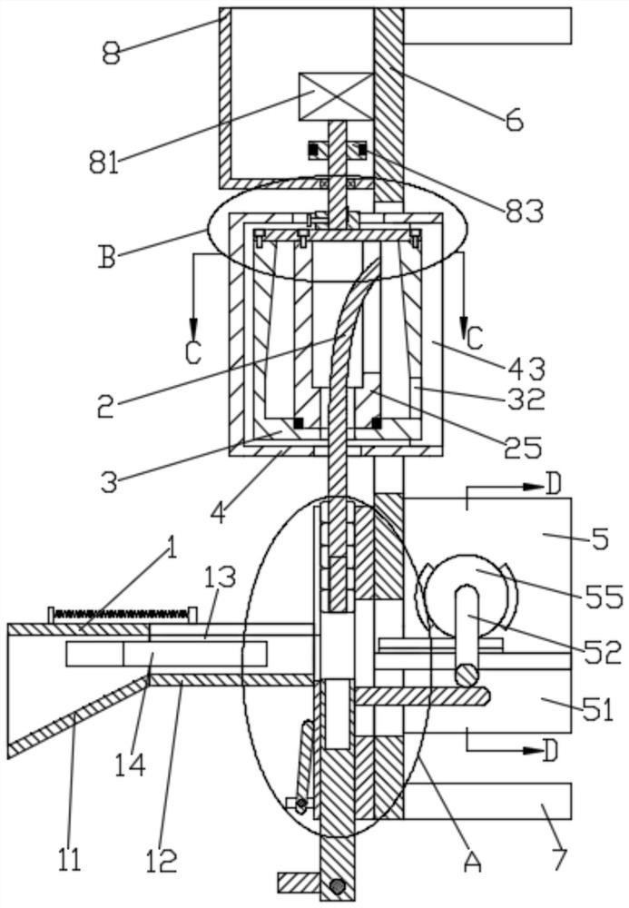
[0030] Such as figure 1 A nut deburring machine and its blanking mechanism shown include a bottom plate 6 on which a blanking mechanism 1, two mutually symmetrical deburring mechanisms 2, two mutually symmetrical oscillation mechanisms 4 and Two mutually symmetrical protective shells 4 also include a first power mechanism 8 and a second power mechanism 5, the first power mechanism 8 provides power for the deburring mechanism 2 and the vibration mechanism 4, the The second power mechanism 5 ensures that the unloading mechanism 1 and the deburring mechanism 2 operate smoothly, and the other end of the bottom plate 6 is fixedly provided with a plurality of legs 7 .

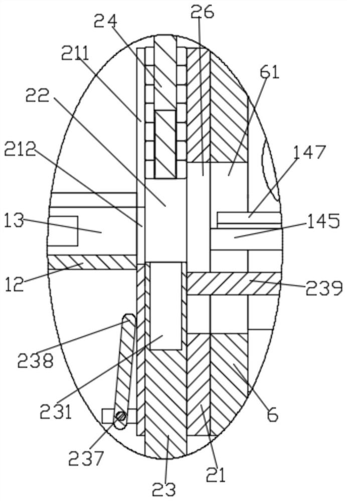
[0031] Such as figure 1 , figure 2 and Figure 7 As shown, the blanking mechanism 1 includes a hopper 11 and a finishing plate 14, two blanking parts 12 protrude on the hopper 11, and the blanking part 12 is provided with a blanking hole 13, and the blanking part 12 is provided with a blanking hole 13. The hole ...

Embodiment 2

[0050] Embodiment 2: as Figure 8 and Figure 9 As shown: the second power mechanism includes a first cylinder 98 and a second cylinder 99, the first cylinder 98 is fixed on the positioning plate, and the extension end of the first cylinder 98 is fixed between the push rod 23 Connecting plate 97 is connected, and described first cylinder 98 drives described ejector rod 23 to realize reciprocating motion through connecting plate 97, and described second cylinder 99 is fixed on described base plate 6, and the extension end of described second cylinder 99 is connected with The finishing board 14 is fixedly connected, and the finishing board 14 is driven to reciprocate by the second cylinder 99 .

[0051] Processing steps:

[0052] Step 1: When unloading, the first cylinder 99 drives the finishing plate 14 to do reciprocating motion and starts discharging, the finishing plate 14 continuously presses the nuts in the hopper 11, so that the nuts fall in an orderly manner The nuts ...

Embodiment 3

[0058] A rotating shaft is provided for rotation and cooperation between the mounting plates 51, and the rotating shaft is power-cooperated with the second motor 54. A cam is fixed on the rotating shaft, and the rotating cam drives the moving plate 239 to move. The rotating shaft A missing-toothed gear 55 is provided on the top, and the limiting rack 147 is driven to move by the missing-toothed gear 55 .


PUM


Abstract

The nut burr removing machine comprises a bottom plate, a hopper and a pair of symmetrical positioning plates, the hopper is used for containing nuts to be machined, the positioning plates are fixed to the bottom plate, the hopper and the positioning plates are fixed together, a pair of symmetrical discharging parts are arranged on the hopper in a protruding mode, and the discharging parts are arranged on the bottom plate. The device further comprises an arrangement assembly, the arrangement assembly comprises an arrangement plate, the arrangement plate is in sliding fit with the hopper, and the arrangement plate reciprocates up and down to guarantee smooth discharging. According to the technical scheme, the nuts are jacked and pressed in a reciprocating mode through the sorting plate, so that the nuts can be smoothly discharged in a neat arrangement mode, the positions of the nuts can be conveniently observed through the peeping groove, the problem is solved, the reciprocating frequency of the sorting plate can be increased through the tooth-missing gear, and the discharging efficiency is improved; the two symmetrical discharging parts can improve the discharging speed.

Description

technical field [0001] The invention relates to the field of nut processing, in particular to a nut deburring machine and a feeding mechanism thereof. Background technique [0002] The anti-theft nut has two symmetrical small grooves in the internal thread of the ordinary nut. When in use, small steel balls are placed in the small grooves, so that the tightened nut cannot be screwed out in reverse. When the anti-theft nut is processed, some small burrs will be generated in the internal thread and the groove, and these small burrs will affect the normal use of the entire nut; after ordinary nuts are tapped, small burrs will appear at the port, and the thread after tapping There will also be a small amount of debris in the hole. The debris and burrs not only make the nut unusable, but also cause loosening after use, which can seriously cause production accidents. Contents of the invention [0003] In order to solve the above problems, the object of the present invention is ...

Claims


Application Information

Patent Timeline
Patent Type & Authority Applications(China)
IPC IPC(8): B23D79/00B23Q7/00
CPCB23D79/00B23Q7/00
Inventor 杨新华
Owner 浙江长城电力设备有限公司
Why Eureka
Try Eureka