Multifunctional surface cleaning machine stable to use
A multi-functional, cleaning machine technology, applied in cleaning machinery, cleaning equipment, manual floor scrubbing machinery, etc., can solve problems such as loud noise and vibration, jamming, unfavorable use experience, etc., to achieve the effect of user-friendly use
- Summary
- Abstract
- Description
- Claims
- Application Information
AI Technical Summary
Problems solved by technology
Method used
Image
Examples
Embodiment 1
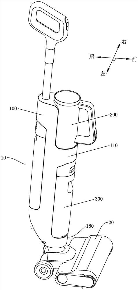
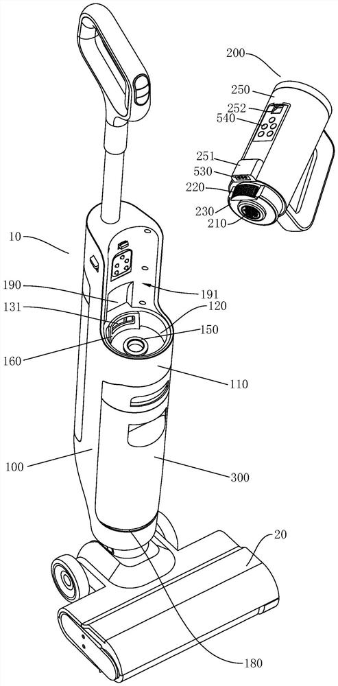
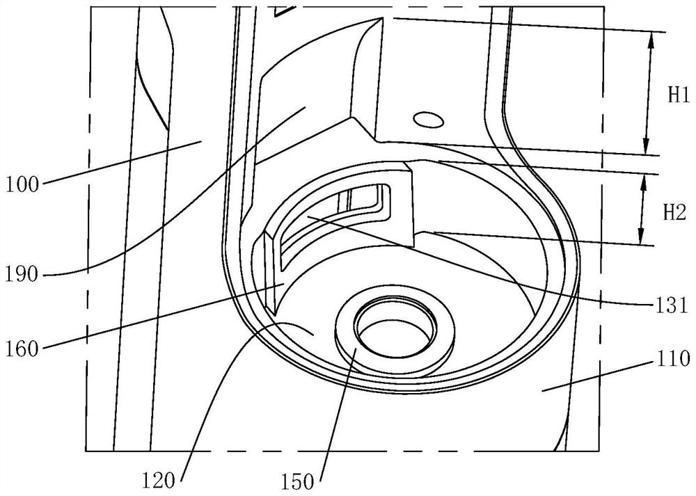
[0043] As a surface cleaning machine described in the present invention, such as Figure 1 to Figure 10 As shown, it includes a body 10 having a positioning portion 110 and a floor brush 20 pivotally connected to the bottom end of the body 10. The positioning portion 110 protrudes outward from the body 10. The upper and lower suction source assemblies 200 and the sewage tub 300. The lower part of the side wall of the suction source assembly 200 is provided with a guiding convex portion 251 , the main body 10 is provided with a guiding concave cavity 190 matched with the guiding convex portion 251 , and the main body 10 is provided with a first extending to the positioning portion 110 . The limiting surface 191 , the guide cavity 190 is disposed on the first limiting surface 191 and located above the positioning portion 10 . When the suction source assembly 200 is installed on the fuselage 10, it can be quickly and smoothly installed in place with the help of the guiding funct...
Embodiment 2
[0070] combine Figure 11 , the inlet 131 of the exhaust cavity 130 is set at the bottom of the positioning cavity 120, the exhaust cavity 130 is set in the positioning part 110 and extends downward, and the outlet 132 of the exhaust cavity 130 is set at the bottom side of the positioning part 110, self-exhausting The suction air flow from the inlet 131 of the cavity 130 into the exhaust cavity 130 is discharged out of the fuselage 10 through the outlet 132 of the exhaust cavity.
[0071] combine Figure 12 The front end of the suction source assembly 200 is provided with a first end face 231 and a second end face 232 that are staggered in front and rear. 220 is disposed on the second end face 232 and is disposed around the air inlet 210 . The air inlet channel 111 is arranged at the center of the positioning portion 110 , the air exhaust cavity 130 is arranged on the outer periphery of the air inlet channel 111 , and the inlets 131 of the air outlet cavity 130 are distribut...
PUM
 Abstract
Description
Claims
Application Information
 - R&D
- Intellectual Property
- Life Sciences
- Materials
- Tech Scout
- Unparalleled Data Quality
- Higher Quality Content
- 60% Fewer Hallucinations
Browse by: Latest US Patents, China's latest patents, Technical Efficacy Thesaurus, Application Domain, Technology Topic, Popular Technical Reports.
© 2025 PatSnap. All rights reserved.Legal|Privacy policy|Modern Slavery Act Transparency Statement|Sitemap|About US| Contact US: help@patsnap.com


