Washing equipment
A technology for washing equipment and containers, which is applied to cleaning equipment, washing devices, tableware washing machines/rinsing machines, etc., and can solve problems such as high prices and unfavorable promotion of one-tub wave-wheel washing machines
- Summary
- Abstract
- Description
- Claims
- Application Information
AI Technical Summary
Problems solved by technology
Method used
Image
Examples
Embodiment 1
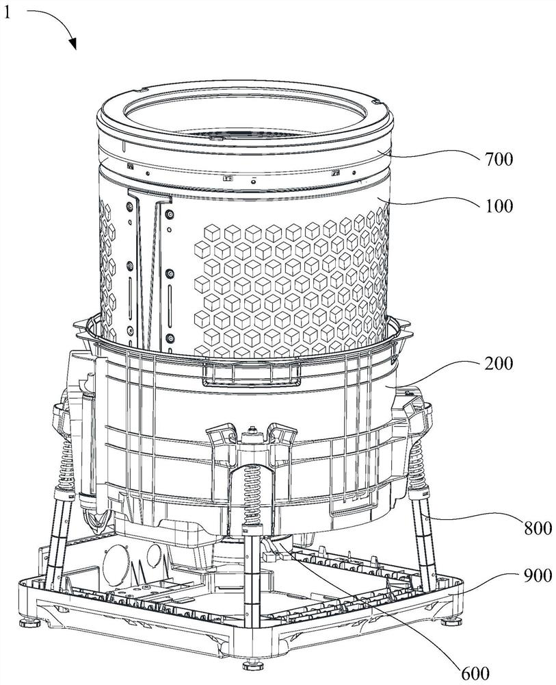
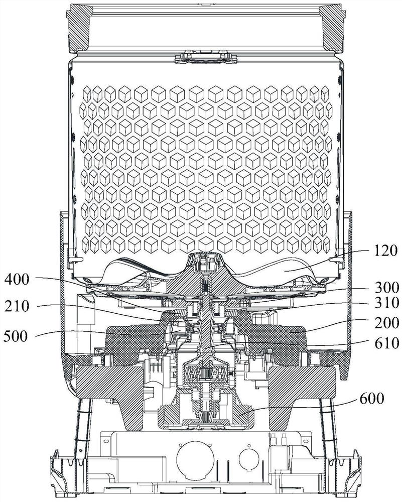
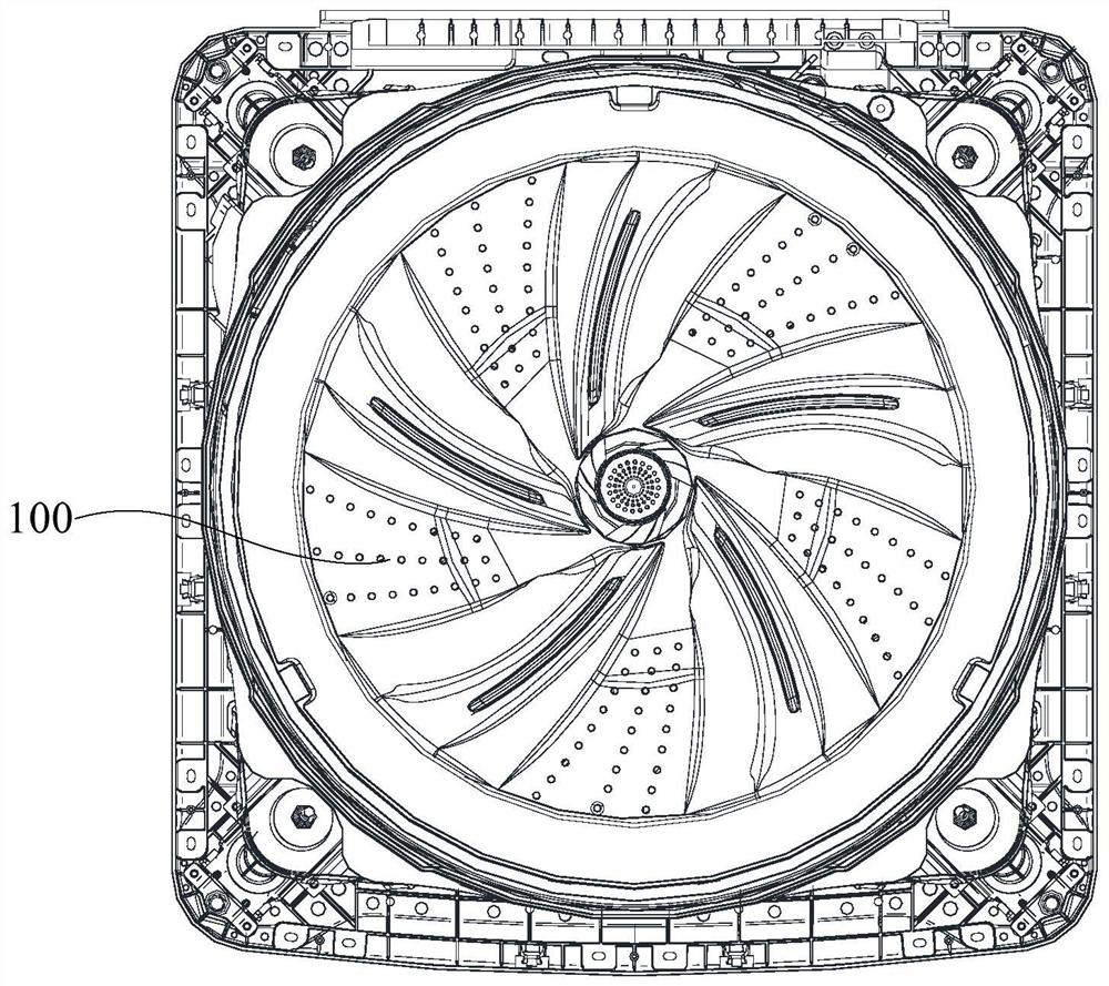
[0118] like figure 1 , figure 2 , image 3 , Figure 4 and Figure 5 As shown, an embodiment of an aspect of the present invention provides a washing device 1 , comprising: a first container 100 , a first drain port is provided at the bottom of the first container 100 ; , the connector 300 includes a sealing rib 310, the sealing rib 310 is located on the outer circumference of the first drain; the second container 200 is sleeved on the outside of the first container 100, and the second container 200 is provided with a second drain 210; the first sealing The sealing rib 310 shields the side of the first sealing member 400 which faces the centerline of the first water outlet.
[0119] The washing device 1 provided by the embodiment of the present invention includes a first container 100 , a second container 200 , a connecting member 300 disposed at the bottom of the first container 100 , and a first sealing member 400 disposed at the second container 200 . Wherein, the fir...
Embodiment 2
[0122] like figure 1 , figure 2 , image 3 , Figure 4 and Figure 5 As shown, a washing device 1 includes: a first container 100, the bottom of the first container 100 is provided with a first drain; a connecting piece 300 is disposed at the bottom of the first container 100, and the connecting piece 300 includes a sealing rib 310, The sealing rib 310 is located on the outer circumference of the first drain port; the second container 200 is sleeved on the outside of the first container 100 , and the second container 200 is provided with a second drain port 210 ; the first sealing member 400 is provided in the second container 200 Facing one end face of the bottom wall of the first container 100 , the sealing rib 310 shields the side of the first sealing member 400 facing the centerline of the first drainage port. Further, the first container 100 can be rotated relative to the second container 200 . Further, a dynamic seal is formed between the sealing rib 310 and the fi...
Embodiment 3
[0130] On the basis of the second embodiment above, it is further defined that the first sealing member 400 includes an oil sealing member.
[0131] In this embodiment, the first sealing member 400 is specifically designed to include an oil sealing member, and the sealing effect is good.
[0132] In some embodiments, the side of the oil seal facing away from the sealing rib 310 is in contact with the groove wall of the installation groove 220 .
[0133] In these embodiments, by making the side of the oil seal facing away from the sealing rib 310 to be in contact with the groove wall of the installation groove 220, on the one hand, the sealing effect can be ensured; Displacement such as rotation occurs in the installation groove 220 , and even falls off from the installation groove 220 .
[0134] Further, the oil seal is fitted in the installation groove 220 by interference.
[0135] In some embodiments, the side of the oil seal facing the sealing rib 310 has a lip seal struc...
PUM
 Abstract
Description
Claims
Application Information
 - R&D
- Intellectual Property
- Life Sciences
- Materials
- Tech Scout
- Unparalleled Data Quality
- Higher Quality Content
- 60% Fewer Hallucinations
Browse by: Latest US Patents, China's latest patents, Technical Efficacy Thesaurus, Application Domain, Technology Topic, Popular Technical Reports.
© 2025 PatSnap. All rights reserved.Legal|Privacy policy|Modern Slavery Act Transparency Statement|Sitemap|About US| Contact US: help@patsnap.com


