
Sampling valve with labyrinth damping structure

A damping structure and sampling valve technology, applied in sampling devices, lift valves, valve devices, etc., can solve the problems of sampling liquid splashing, sampling valve clogging, and difficulty in controlling the outlet pressure of sampling water, so as to achieve convenient use and improve safety. The effect of improving the efficiency of sampling work

Active Publication Date: 2022-06-03
长春电子科技学院
View PDF5 Cites 0 Cited by
  • Summary
  • Abstract
  • Description
  • Claims
  • Application Information

AI Technical Summary

Problems solved by technology

[0004] The object of the present invention is to provide a sampling valve with a labyrinth damping structure, to solve the problem that the existing sampling valve with a labyrinth damping structure proposed in the above background technology is in use, because impurities directly enter the sampling valve and the sampling water flows out of the outlet. The pressure is difficult to control, which leads to the problem that the sampling valve is easy to block and the sample liquid is prone to splashing

Method used


Image

  • Sampling valve with labyrinth damping structure
  • Sampling valve with labyrinth damping structure
  • Sampling valve with labyrinth damping structure

Examples


Embodiment Construction

[0029] The technical solutions in the embodiments of the present invention will be clearly and completely described below with reference to the accompanying drawings in the embodiments of the present invention.

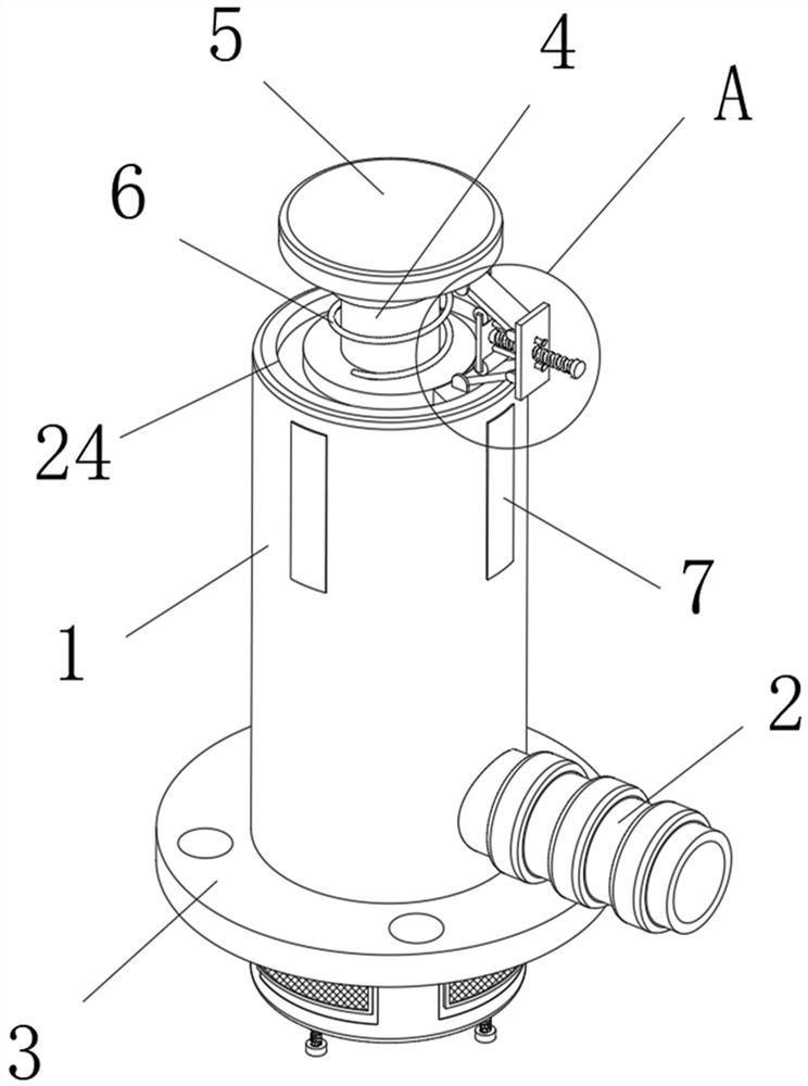
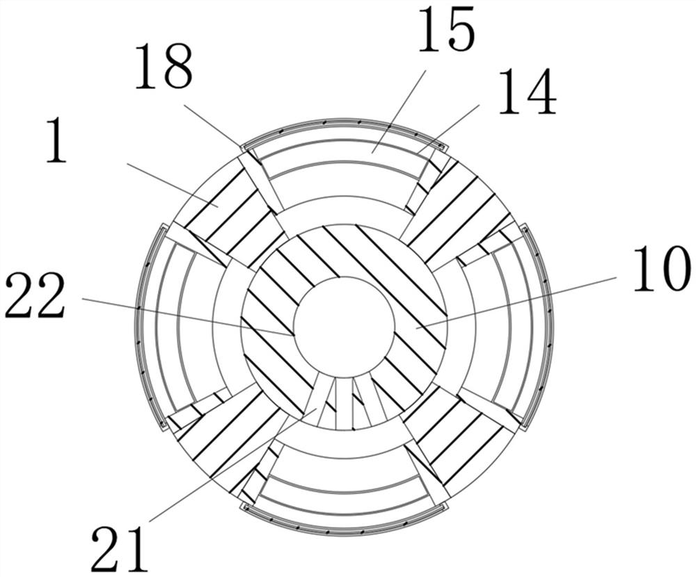
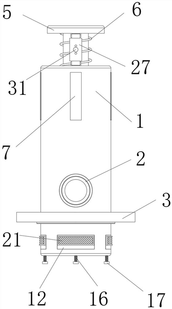
[0030] see Figure 1-9, the present invention provides a technical solution: a sampling valve with a labyrinth damping structure, comprising a sampling valve housing 1, a water outlet pipe 2 is fixedly connected to the right side of the sampling valve housing 1, and a water outlet pipe 2 is fixedly installed on the lower part of the outer side of the sampling valve housing 1. Connecting flange 3, the top of the sampling valve shell 1 is movably installed with a valve stem 4, the upper end of the valve stem 4 is fixedly installed with a control knob 5, the lower end of the valve stem 4 is located in the inner cavity of the sampling valve shell 1, and the lower end of the valve stem 4 is fixedly installed with a The valve core 8, the left and right sides of the lower su...


PUM


Abstract

The sampling valve with the labyrinth damping structure comprises a sampling valve shell, a water outlet pipe is fixedly connected to the right side of the sampling valve shell, a connecting flange is fixedly installed on the lower portion of the outer side of the sampling valve shell, a valve rod is movably installed at the top of the sampling valve shell in a penetrating mode, and a control knob is fixedly installed at the upper end of the valve rod. The lower end of the valve rod is located in an inner cavity of the sampling valve shell, a valve element is fixedly installed at the lower end of the valve rod, telescopic rods are fixedly installed on the left side and the right side of the lower surface of the valve element correspondingly, and a rotary blocking block is fixedly connected to the lower ends of the two telescopic rods jointly and movably installed at the bottom of the inner cavity of the sampling valve shell. A connecting groove is formed in the upper surface of the rotary blocking block, and three water inlet holes are formed in the surface of an inner cavity of the connecting groove. The pressure of the sampling liquid outlet can be conveniently adjusted, unnecessary troubles caused by liquid splashing are prevented, and the sampling valve can be effectively prevented from being blocked.

Description

technical field [0001] The invention belongs to the technical field of sampling valves, in particular to a sampling valve with a labyrinth damping structure. Background technique [0002] Sampling valve is a valve used to obtain medium samples in pipelines or equipment. In many occasions where chemical analysis of medium samples is required, special sampling valves are often used. According to different working principles or performance during sampling, sampling valves are mainly used. There are three types, including double-opening valve, flange-clamped valve and sampling valve with insulation jacket. Many sampling valves are connected with pipelines through flanges, and the samples can be taken out directly by controlling the sampling valve when sampling is required. [0003] Existing sampling valves mostly use control valve core height so that the water inlet and outlet are connected to complete the sampling work. When the sampling valve is sampling, if there are solid im...

Claims


Application Information

Patent Timeline
Patent Type & Authority Applications(China)
IPC IPC(8): F16K3/32F16K1/32F16K51/00B01D35/04F16K31/60F16K37/00F16K47/08G01N1/10
CPCF16K3/32F16K1/32F16K51/00B01D35/04F16K31/60F16K37/00F16K47/08G01N1/10Y02E30/30
Inventor 郝芯侯蕾郭永峰苏东楠赵晶吴翠红王蕾
Owner 长春电子科技学院
Learn More