Buffer valve structure

A buffer mechanism and valve technology, which is applied in the direction of the valve housing structure, balance valve, valve device, etc., can solve problems such as blockage of the connecting device, medium affecting the safety of the connecting device, etc., and achieve the effect of improving safety and convenience

Pending Publication Date: 2022-06-03
田继峰
View PDF0 Cites 0 Cited by
  • Summary
  • Abstract
  • Description
  • Claims
  • Application Information

AI Technical Summary

Problems solved by technology

[0005] The invention provides a buffer valve structure, one of which is to have an effective buffer function and solve the problem that the violent flow of the medium will affect the safety of the connection device; the other purpose is to solve the problem that impurities can easily cause the internal There is a problem of clogging, so as to achieve the effect of filtering out impurities

Method used


Image

  • Buffer valve structure
  • Buffer valve structure
  • Buffer valve structure

Examples


Embodiment 1

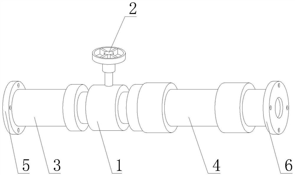
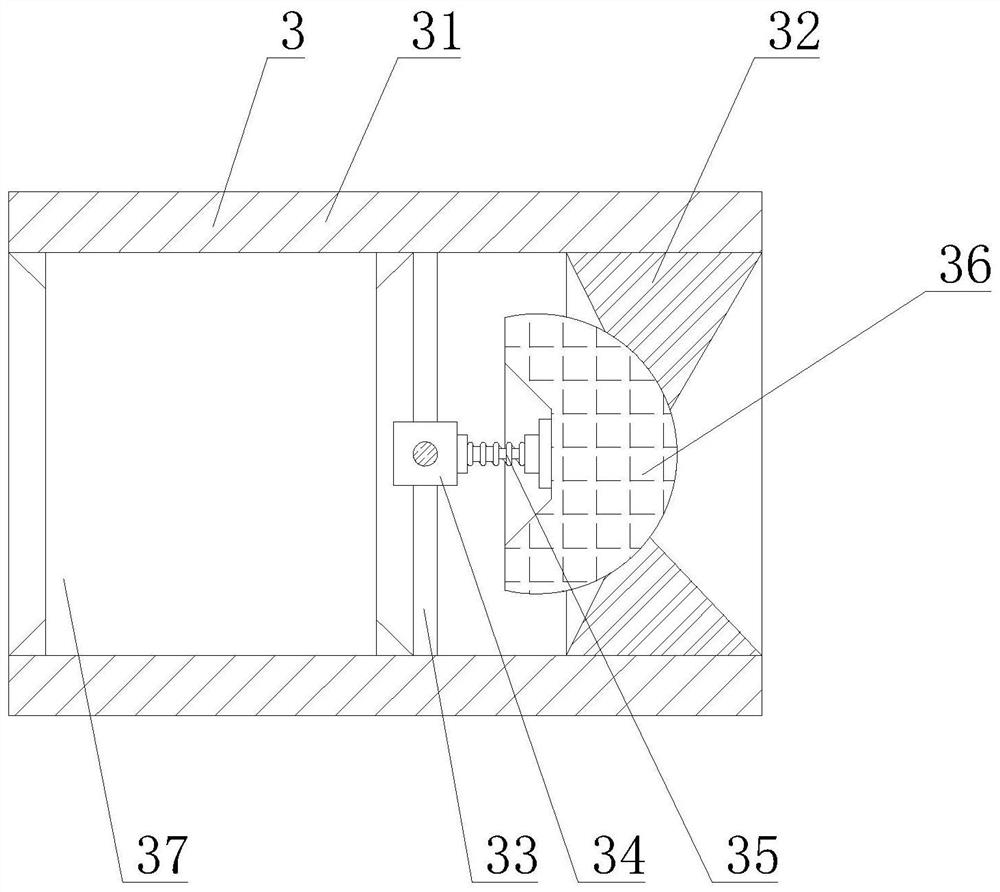
[0034] like Figure 1-8As shown, the present invention provides a buffer valve structure, comprising a valve body 1, a control handle 2 is arranged on the top of the valve body 1, a multi-stage buffer mechanism 3 is arranged on the left side of the valve body 1, and a right side of the valve body 1 is arranged A filter protection mechanism 4 is provided. The multi-stage buffer mechanism 3 includes a buffer tube body 31. The buffer tube body 31 is fixedly connected to the left side of the valve body 1. The left side of the buffer tube body 31 is fixedly welded with an output connection flange 5. The buffer tube The inner wall of the body 31 is fixedly welded with a fitting inner ring 32, and the inner wall of the buffer tube body 31 is fixedly welded with a fixing rod 33 located on the left side of the fitting inner ring 32, and one end of the fixing rod 33 away from the inner wall of the buffer tube body 31 is fixedly welded with a middle The position block 34, the right side ...

Embodiment 2

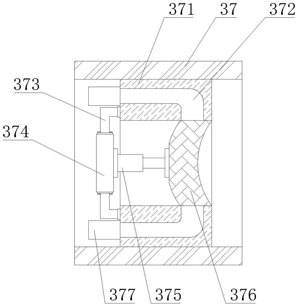
[0036] like Figure 1-8 As shown, on the basis of Embodiment 1, the present invention provides a technical solution: preferably, a secondary buffer tube 37 is fixedly installed on the inner wall of the fitting inner ring 32, and a welded joint is fixed on the inner wall of the secondary buffer tube 37. In the inner ring 371, the inner wall of the welding inner ring 371 is provided with a buffer shunt groove 372, and the end of the buffer shunt groove 372 away from the inner wall of the welding inner ring 371 extends to the left side of the welding inner ring 371, and the left side of the welding inner ring 371 is fixedly welded with a Bending rod 373, one end of the bending rod 373 away from the welding inner ring 371 is fixedly mounted with a base plate 374, the right side of the base plate 374 is fixedly mounted with a fixing cylinder 375, and the left side of the welding inner ring 371 is fixedly connected to the left side of the buffer shunt 372. The branch buffer cylinder...

Embodiment 3

[0038] like Figure 1-8 As shown, on the basis of Embodiment 1, the present invention provides a technical solution: preferably, a fixed bottom box 3771 is fixedly welded on the inner wall of the branch buffer cylinder 377, and a sliding protrusion is slidably connected to the inner cavity of the fixed bottom box 3771. Lifting block 3772, a silicone elastic block 3773 is fixedly installed on the inner wall of the fixed bottom box 3771, the side of the silicone elastic block 3773 away from the inner wall of the fixed bottom box 3771 is fixedly connected with the sliding protrusion block 3772, and the outer wall of the branch buffer cylinder 377 is fixedly installed There is an outstretching box 3774, an elastic foot 2 3775 is fixedly installed on the inner wall of the outreach box 3774, and a buffer closing plate 3777 is fixedly connected to the movable end of the elastic foot 2 3775, and the buffer closing plate 3777 extends away from the end of the second elastic foot 3775. T...


PUM


Abstract

The invention discloses a buffer valve structure, and relates to the technical field of valve devices, the buffer valve structure comprises a valve body, the top of the valve body is provided with a control rotating handle, the left side of the valve body is provided with a multi-stage buffer mechanism, the right side of the valve body is provided with a filter protection mechanism, and the multi-stage buffer mechanism comprises a buffer pipe body. After the valve body is opened by controlling the rotating handle, a medium can rapidly flow into an inner cavity of the buffer pipe body under the action of original pressure, the pressure of the medium is converted into pushing force for the wedging mushroom head, the function of primarily buffering the pressure is achieved through the first elastic foot, and the medium subjected to primary buffering can enter an inner cavity of the second-stage buffer pipe; when the medium flows, the medium generates thrust on the sliding buffer plate, the sealing sliding block is promoted to slide in the inner cavity of the fixing barrel, meanwhile, the water solution is compressed into the inner cavity of the elastic rubber bag, the medium is buffered for the second time, and the problem that the safety of the connecting device is affected due to violent flowing of the medium is solved.

Description

technical field [0001] The invention relates to a valve structure, and relates to the technical field of valve devices, in particular to a buffer valve structure. Background technique [0002] The valve is a pipeline accessory used to open and close the pipeline, control the flow direction, and adjust and control the parameters of the conveying medium. According to its function, it can be divided into shut-off valve, check valve, regulating valve, etc. The control part has the functions of cut-off, regulation, diversion, prevention of backflow, voltage regulation, shunt or overflow and pressure relief. Valves used in fluid control systems, from the simplest shut-off valve to various valves used in extremely complex automatic control systems, have a wide variety and specifications. Valves can be used to control air, water, steam, various corrosive media, The flow of various types of fluids such as mud, oil, liquid metals and radioactive media. The following problems exist f...

Claims


Application Information

Patent Timeline
IPC IPC(8): F16K17/30F16K17/28F16K27/02F16K31/60B01D29/35B01D29/64B01D29/68B01D35/04
CPCF16K17/30F16K17/28F16K27/0209F16K31/60B01D29/35B01D29/6407B01D29/6415B01D29/68B01D35/04
Inventor 田继峰
Owner 田继峰
Why Eureka
Try Eureka