
Spatial offset Raman spectrum detection system

A technology of Raman spectrum detection and spatial offset, applied in Raman scattering, material excitation analysis, etc., can solve the problem of weak Raman signal, reduce workload, reduce signal intensity difference, and avoid measurement error

Pending Publication Date: 2022-06-03
上海近观科技有限责任公司
View PDF0 Cites 0 Cited by
  • Summary
  • Abstract
  • Description
  • Claims
  • Application Information

AI Technical Summary

Problems solved by technology

[0005] In view of the above-mentioned shortcomings of the prior art, the object of the present invention is to provide a spatially offset Raman spectroscopy detection system, which is used to solve the problem that the larger the spatial offset of the SORS technology in the prior art, the weaker the Raman signal is. question

Method used


Image

  • Spatial offset Raman spectrum detection system
  • Spatial offset Raman spectrum detection system
  • Spatial offset Raman spectrum detection system

Examples


Embodiment Construction

[0043] The embodiments of the present invention are described below through specific specific examples, and those skilled in the art can easily understand other advantages and effects of the present invention from the contents disclosed in this specification. The present invention can also be implemented or applied through other different specific embodiments, and various details in this specification can also be modified or changed based on different viewpoints and applications without departing from the spirit of the present invention.

[0044]When describing the embodiments of the present invention in detail, for the convenience of explanation, the cross-sectional views showing the device structure will not be partially enlarged according to the general scale, and the schematic diagrams are only examples, which should not limit the protection scope of the present invention. In addition, the three-dimensional spatial dimensions of length, width and depth should be included in...


PUM


Abstract

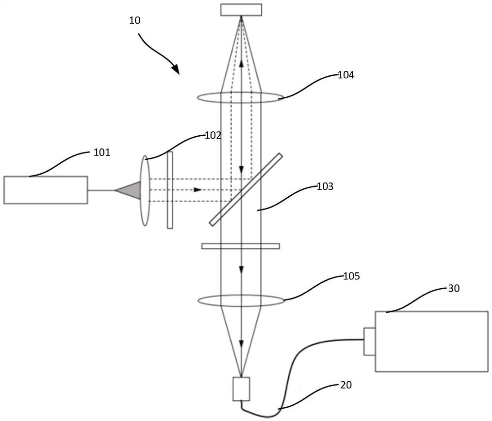
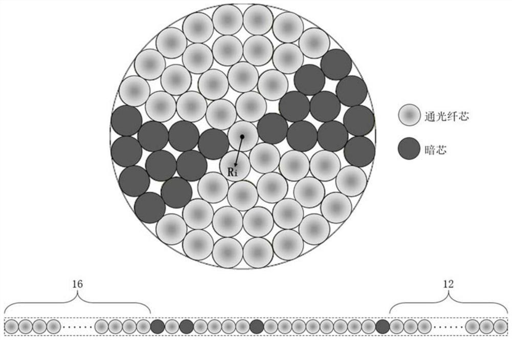
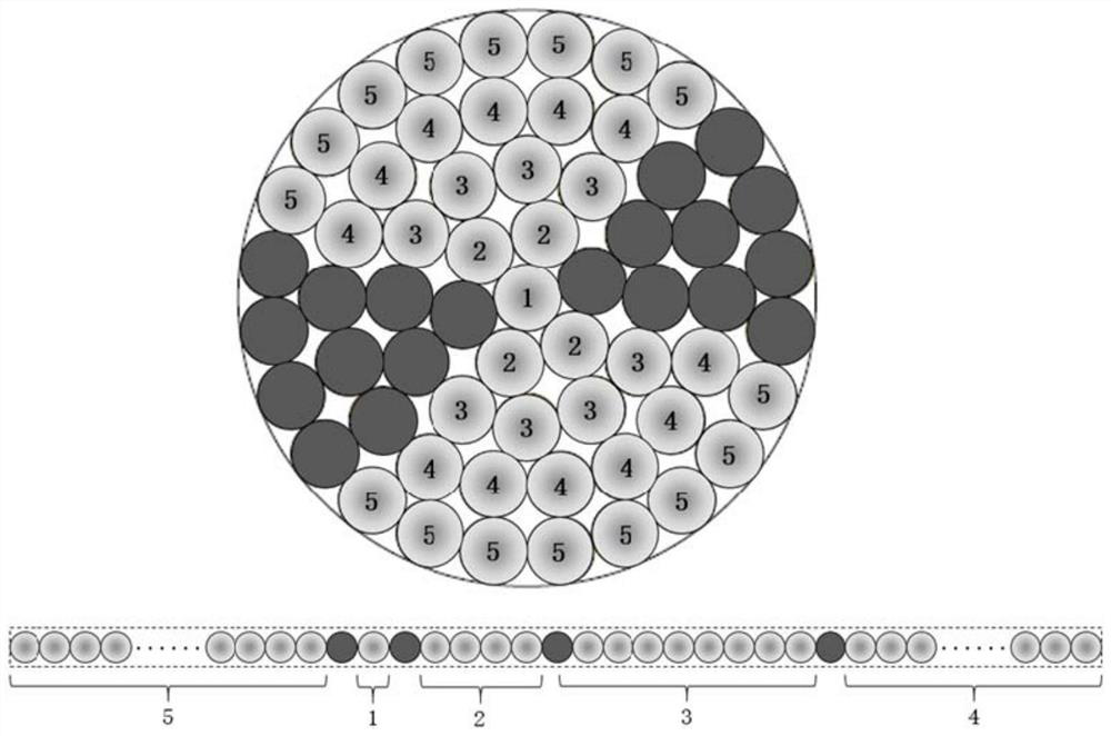
The invention provides a spatial offset Raman spectrum detection system, which is characterized in that an SORS light path device is used for collecting Raman signals and focusing the Raman signals to an input end of a collection optical fiber bundle; the collection optical fiber bundle comprises a circular input end and a linear output end, the circular input end is used for receiving an offset Raman signal focused by the SORS light path device from a sample, and the diameter of the collection optical fiber bundle or / and the number of collection optical fibers contained in the collection optical fiber bundle are / is increased along with the increase of the space offset by taking an excitation position as an original point; the Raman signal which is weakened along with the increase of the space offset is compensated; and the optical fiber bundle linear output end is used for converting the circular arrangement of the circular input end into linear arrangement and is coupled with an entrance slit of the spectrograph. According to the invention, the problem of weak Raman signal intensity at a large spatial offset position in a conventional SORS device or a light path can be effectively solved, and the signal intensity difference between the zero position and the maximum position of the spatial offset is reduced.

Description

technical field [0001] The invention relates to a spectrum detection device, in particular to a spatially shifted Raman spectrum detection system. Background technique [0002] Raman spectroscopy can reflect the vibrational information of material molecules and has good chemical specificity, so it is widely used in the fields of food, medicine and biological detection. Traditional Raman spectroscopy can only detect information on the surface of a sample, or through transparent surfaces. The new Spatially Offset Raman Spectroscopy (SORS) was first proposed by British scientist A.W. Parker in 2005 (related patent numbers: US7652763, CN101115987, EP1828753, US7911604, GB2457212, AU2005313145, JP5449712007). SORS can penetrate the opaque sample surface or outer packaging to obtain chemical information carried by deeper substances. Therefore, spatially offset Raman spectroscopy has a wide range of applications in non-destructive deep detection, such as non-invasive detection of...

Claims


Application Information

Patent Timeline
Patent Type & Authority Applications(China)
IPC IPC(8): G01N21/65
CPCG01N21/65
Inventor 陈昌高钰勇
Owner 上海近观科技有限责任公司
Learn More