
Method and device for eliminating mirror image in grid detection based on centroid search

A grid and centroid technology, applied in the field of radar signal joint detection, can solve problems such as inability to identify mirrored targets and real targets, inaccurate mirror image elimination, and decreased detection performance, so as to avoid increased computation, reduce the number of grids, The effect of improving accuracy

Active Publication Date: 2022-07-22
INFORMATION SCI RES INST OF CETC
View PDF0 Cites 0 Cited by
  • Summary
  • Abstract
  • Description
  • Claims
  • Application Information

AI Technical Summary

Problems solved by technology

[0003] For mirror targets and real targets with the same Signal-Noise Ratio (SNR, Signal-Noise Ratio) value, the existing grid detection mirror removal method usually selects the first stored target as the real target, however, this method cannot identify the SNR value The same mirror target is the same as the real target, which makes the mirror removal inaccurate, resulting in a decrease in detection performance
In addition, in order to improve the accuracy of grid detection in the existing technology, small-size grids are usually selected for detection. However, since the smaller the size of the grid in the same space, the more the number of grids, therefore, the selection of small-size grids for detection will make The amount of computation increases and leads to a decrease in detection performance

Method used


Image

  • Method and device for eliminating mirror image in grid detection based on centroid search
  • Method and device for eliminating mirror image in grid detection based on centroid search
  • Method and device for eliminating mirror image in grid detection based on centroid search

Examples


Embodiment Construction

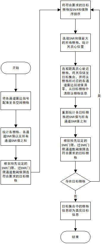
[0051] In the prior art, due to the different positions and viewing angles of each radar node, the shape of the space unit is usually not only complex but also irregular, so that the grid unit can only approximate the space unit. However, in the process of signal spatiotemporal registration, the target signal may be simultaneously registered to multiple grids near the real position of the target, forming multiple mirror targets with the same signal-to-noise ratio as the real target. Identifying and mirroring targets to improve detection performance. For this reason, the grid detection mirror removal method in the prior art usually takes the first grid stored in sequence as the real target, and the grid detection mirror removal method includes the following steps:

[0052] Step S0: register each channel radar signal to each spatial grid.

[0053] Step S1: Count the SNR value of each channel of each grid and the sum of the SNRs of all channels to prepare for screening grids wit...


PUM


Abstract

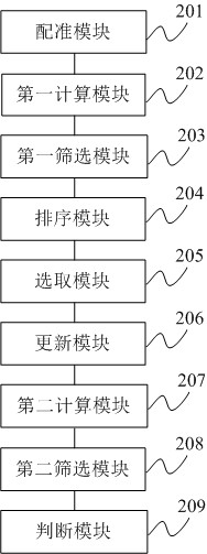
The present disclosure relates to the field of radar signal joint detection, and provides a method and device for grid detection mirror elimination based on centroid search. The method includes: registering each channel radar signal to each spatial grid; calculating the signal noise of each channel of each grid ratio and the sum of signal-to-noise ratio; filter out the target grid array that meets the preset requirements; sort the elements in the target grid array in descending order according to the sum of signal-to-noise ratio; select all grids with the largest sum of signal-to-noise ratio and calculate their centroids ; Save the grid closest to the centroid into the target set, update the echo data of each channel and delete the grid from the target grid array; calculate the signal-to-noise ratio and signal-to-noise ratio of each channel of each grid in the target grid array sum; filter the target grids that meet the preset requirements; determine whether the target grid exists, if so, return to the sorting step, otherwise, the target set contains information as the real target information. The present disclosure can improve the accuracy of mirror image elimination and grid detection accuracy, reduce the number of grids and thus reduce the amount of computation.

Description

technical field [0001] The present disclosure relates to the technical field of radar signal joint detection, and in particular, to a method and device for removing mirror images in grid detection based on centroid search. Background technique [0002] The grid-based joint detection is a radar multi-channel signal fusion detection method. It divides the space into many grid areas, and matches the echo signal distance units of each channel according to the relative radar position of each grid area and the two-way delay of the signal. To each spatial grid, the signal registration and fusion is completed, and then the target is detected according to the fusion signal of each grid to complete the joint detection. [0003] For the mirror target and the real target with the same signal-to-noise ratio (SNR, Signal-Noise Ratio) value, the existing grid detection mirror removal method usually selects the first target stored as the real target. However, this method cannot identify the...

Claims


Application Information

Patent Timeline
Patent Type & Authority Patents(China)
IPC IPC(8): G01S7/41G01M1/12
CPCG01S7/41G01M1/122
Inventor 宋扬吕文超葛建军刘光宏韩阔业武艳伟裴晓帅王欢
Owner INFORMATION SCI RES INST OF CETC
Learn More