Processing device applied to carbon brush structure on brush motor

A technology of processing devices and brushed motors, which is applied in the direction of grinding drive devices, metal processing equipment, grinding machine tools, etc., can solve the problems of reducing the overall production and processing efficiency and troubles of carbon brush structures, and achieve improved processing effects, Improve stability and improve the effect of use

Inactive Publication Date: 2022-06-03
江苏众联祥博新能源科技有限公司
View PDF0 Cites 2 Cited by
  • Summary
  • Abstract
  • Description
  • Claims
  • Application Information

AI Technical Summary

Problems solved by technology

[0004] In the production and processing process of brushed motors, carbon brushes are relatively important processing parts. Therefore, the processing efficiency of carbon brush structures will determine the production efficiency of brushed motors; most of the existing carbon brush structure production and processing processes are manual. Move the carbon brush to the grinding position and use the grinding mechanism for manual grinding. After grinding, manually assemble the polished carbon brush and carbon brush frame. After assembly, move to the detection station for power-on detection. The processing of the structure is troublesome, which greatly reduces the overall production and processing efficiency of the carbon brush structure. Therefore, we propose a processing device for the carbon brush structure applied to the brushed motor to solve the above problems

Method used


Image

  • Processing device applied to carbon brush structure on brush motor
  • Processing device applied to carbon brush structure on brush motor
  • Processing device applied to carbon brush structure on brush motor

Examples


Embodiment

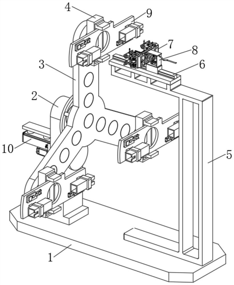
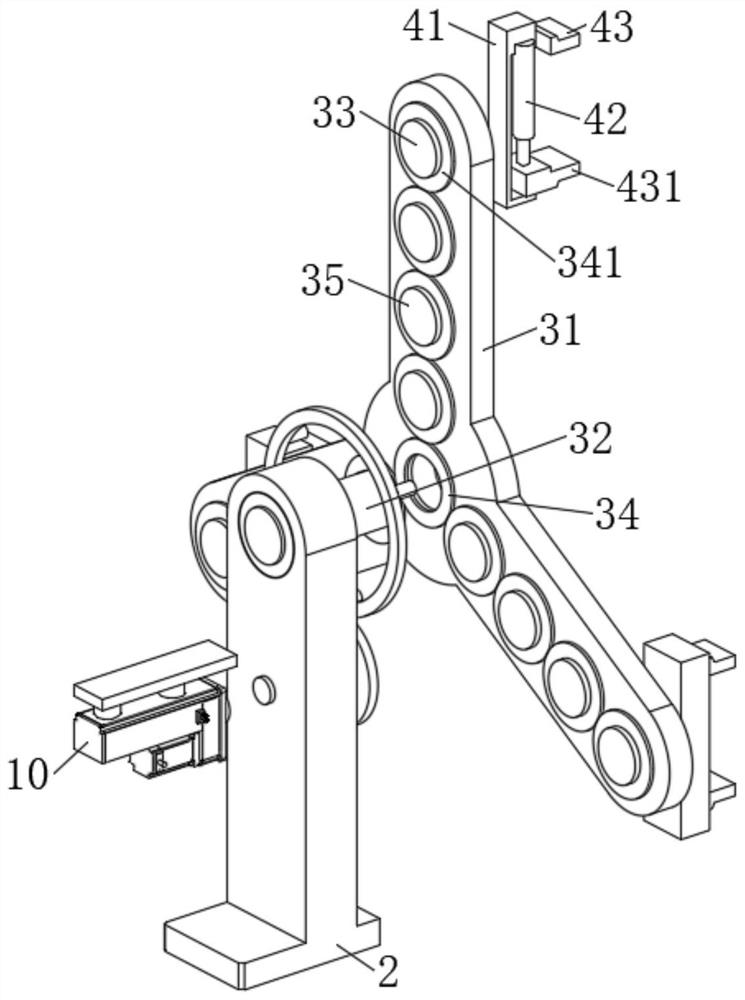
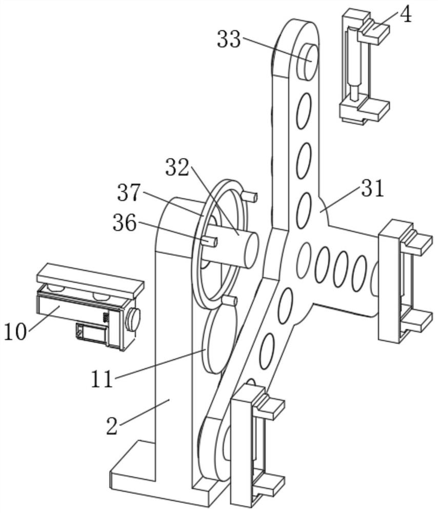
[0031] Example: as Figure 1-8 As shown, the present invention provides a processing device for a carbon brush structure applied to a brushed motor, comprising a bottom plate 1, a bracket 2 is fixedly installed on the top side of the bottom plate 1, and an indexing mechanism 3 is arranged on the top of the bracket 2, The side of the indexing mechanism 3 away from the bracket 2 is provided with a positioning assembly 4, and the positioning assembly 4 is provided with a carbon brush holder frame 9. When in use, the carbon brush can be assembled in the carbon brush holder frame 9 to form a carbon brush structure. The bottom plate 1 A support frame 5 is fixedly installed on the side of the top away from the bracket 2, and a linear electric cylinder 6 is fixedly installed at the top of the supporting frame 5. The driving end of the linear electric cylinder 6 is provided with a card drive assembly 7. The linear electric cylinder 6 and the card drive assembly 7 There is a grinding as...


PUM


Abstract

The invention discloses a machining device applied to a carbon brush structure on a brush motor, and particularly relates to the technical field of motor part machining, the machining device comprises a bottom plate, a support is fixedly installed on one side of the top end of the bottom plate, an indexing mechanism is arranged on the top of the support, and a positioning assembly is arranged on the side, away from the support, of the indexing mechanism; according to the invention, the transposition mechanism and the positioning assembly are arranged, and the first motor is used in cooperation, so that the position of the positioning assembly can be driven to change without autorotation, the station of the positioning assembly can be flexibly changed, and the positioning assembly is convenient to use. Orderly and automatic polishing, assembling and detecting of a plurality of carbon brushes can be conveniently realized, so that the use effect of the whole carbon brush structure is improved; and by arranging the clamping and driving assembly, roller type positioning can be conveniently conducted on the carbon brushes of different sizes, the stability of the subsequent carbon brush polishing machining is improved, and the carbon brushes can be conveniently driven to horizontally move to be automatically assembled in the subsequent process.

Description

technical field [0001] The invention relates to the technical field of motor parts processing, in particular to a processing device of a carbon brush structure applied to a brushed motor. Background technique [0002] A brushed motor is a rotating electrical machine that converts electrical energy into mechanical energy (motor) or converts mechanical energy into electrical energy (generator) with built-in brush devices. The brushed motor is the basis of all motors, and has the characteristics of fast starting, timely braking, smooth speed regulation in a wide range, and relatively simple control circuit; [0003] The brushed motor is composed of two parts: the stator and the rotor. The stator has magnetic poles (winding or permanent magnet type), and the rotor has windings. After electrification, a magnetic field (magnetic pole) is also formed on the rotor. The included angle makes the motor rotate under the mutual attraction of the stator and rotor magnetic fields (between...

Claims


Application Information

Patent Timeline
Patent Type & Authority Applications(China)
IPC IPC(8): H01R43/12B24B19/00B24B27/00B24B41/06B24B47/00B24B55/06B24B55/12
CPCH01R43/12B24B19/00B24B41/06B24B47/00B24B27/0023B24B55/06B24B55/12H01R2201/10
Inventor 赵娜龚雪丹唐海龙胡心彬
Owner 江苏众联祥博新能源科技有限公司
Why Eureka
Try Eureka