Driving circuit system of ultrasonic transducer and self-adaptive frequency modulation method

A driving circuit and ultrasonic technology, applied in electrical components, high-efficiency power electronic conversion, output power conversion devices, etc., can solve the problems of increasing difficulty of driving circuits, large number of components, and increased cost, and achieve less difficulty in hardware technology. , The effect of wide frequency adjustment range and small number of components

Pending Publication Date: 2022-06-03
浙江台州蓝浦智能科技有限公司
View PDF0 Cites 2 Cited by
  • Summary
  • Abstract
  • Description
  • Claims
  • Application Information

AI Technical Summary

Problems solved by technology

Due to the high operating frequency of the ultrasonic transducer, the adoption of this technical solution requires relatively high hardware configuration, high precision requirements for components, and high quality requirements for feedback signals, which will increase the difficulty and cost of the entire drive circuit. At the same time, the frequency range tracked by the phase-locked loop drive control circuit is relatively narrow, and the number of components is large, which cannot meet the requirements of the application in this product.

Method used


Image

  • Driving circuit system of ultrasonic transducer and self-adaptive frequency modulation method
  • Driving circuit system of ultrasonic transducer and self-adaptive frequency modulation method
  • Driving circuit system of ultrasonic transducer and self-adaptive frequency modulation method

Examples


Embodiment Construction

[0029] The technical solutions in the embodiments of the present invention will be clearly and completely described below with reference to the accompanying drawings in the embodiments of the present invention.

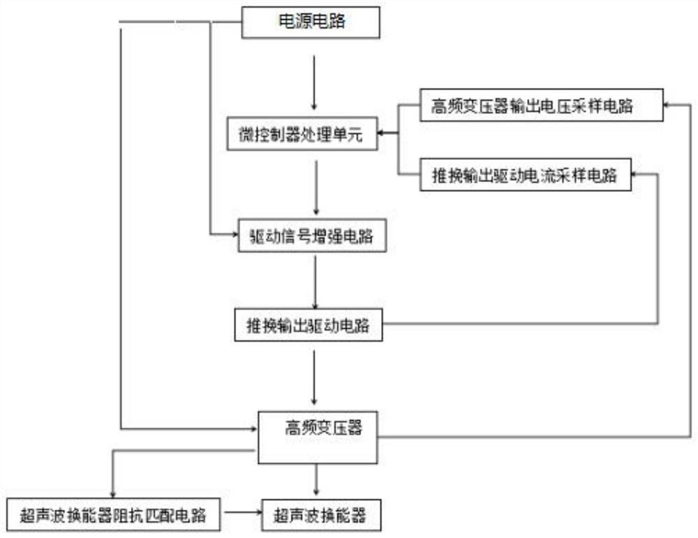
[0030] refer to Figure 1-3 , an embodiment provided by the present invention: a drive circuit system of an ultrasonic transducer, the drive circuit system is used to adjust the drive frequency of the ultrasonic transducer operation, so that the ultrasonic transducer works in the resonant frequency state , including a microcontroller processing unit, a drive signal enhancement circuit, a push-pull output drive circuit, a high-frequency transformer, an impedance matching circuit for an ultrasonic transducer, a push-pull output drive current sampling circuit, a high-frequency transformer output voltage sampling circuit, and a power supply circuit;

[0031] Microcontroller processing unit, real-time sampling of the working voltage of the ultrasonic transducer (that is, t...


PUM


Abstract

The invention discloses a driving circuit system of an ultrasonic transducer and a self-adaptive frequency modulation method, and the driving circuit system is used for adjusting the working driving frequency of the ultrasonic transducer. Comprising a microcontroller processing unit, a driving signal enhancement circuit, a push-pull output driving circuit, a high-frequency transformer, an ultrasonic transducer impedance matching circuit, a push-pull output driving current sampling circuit, a high-frequency transformer output voltage sampling circuit and a power supply circuit. The self-adaptive frequency modulation method comprises the following steps: the microcontroller processing unit searches the resonant working frequency of the ultrasonic transducer in the working environment in an initial state through the driving circuit; in the working state, the ultrasonic transducer is adjusted to the resonant frequency in a self-adaptive mode. According to the invention, the self-adaptive dynamic frequency adjustment of the ultrasonic transducer is realized, and manual tuning is not needed; meanwhile, as the frequency range is F0 + / -FC, the frequency adjusting range is wide, and in addition, the hardware technology difficulty is small, the number of components is small, and the cost is low.

Description

technical field [0001] The invention relates to the technical field of ultrasonic transducer operating frequency control, in particular to a drive circuit system of an ultrasonic transducer and an adaptive frequency modulation method. Background technique [0002] The traditional ultrasonic transducer drive circuit uses inductors, piezoelectric ceramics, etc. to form an LC oscillation circuit. When the impedance of the ultrasonic transducer matches the oscillation circuit, it works at the resonant frequency. When the use environment of ultrasonic waves changes, the optimal resonance frequency of the ultrasonic transducer cannot be satisfied, and the optimal working state of the ultrasonic transducer can only be satisfied by manual tuning. [0003] Among the existing ultrasonic transducer driving technical solutions, there is also a method of using a hardware phase-locked loop driving control circuit to track the operating frequency of the ultrasonic transducer. Due to the h...

Claims


Application Information

Patent Timeline
Patent Type & Authority Applications(China)
IPC IPC(8): H02M7/538H02M7/5395H02M1/36H02M1/08
CPCH02M7/53803H02M7/5395H02M1/36H02M1/08Y02B70/10
Inventor 舒果
Owner 浙江台州蓝浦智能科技有限公司
Why Eureka
Try Eureka