Arthroscopic surgery auxiliary device for orthopedics department

A technique for arthroscopic surgery and an auxiliary device, applied in the field of arthroscopy, can solve the problems of arthroscopic falling off, troublesome use, etc., and achieve the effects of facilitating docking and positioning, preventing sliding, and connecting and tightening

Inactive Publication Date: 2022-06-07
楚亚杰
View PDF0 Cites 1 Cited by
  • Summary
  • Abstract
  • Description
  • Claims
  • Application Information

AI Technical Summary

Problems solved by technology

[0003] At present, when the arthroscope is fixed, most of the arthroscope is fixed in the docking position through thread connection, but when the force is opposite to the direction of the thread line, it is easy to cause the arthroscope to fall off, which brings troubles to people's use

Method used


Image

  • Arthroscopic surgery auxiliary device for orthopedics department
  • Arthroscopic surgery auxiliary device for orthopedics department
  • Arthroscopic surgery auxiliary device for orthopedics department

Examples


Embodiment 1

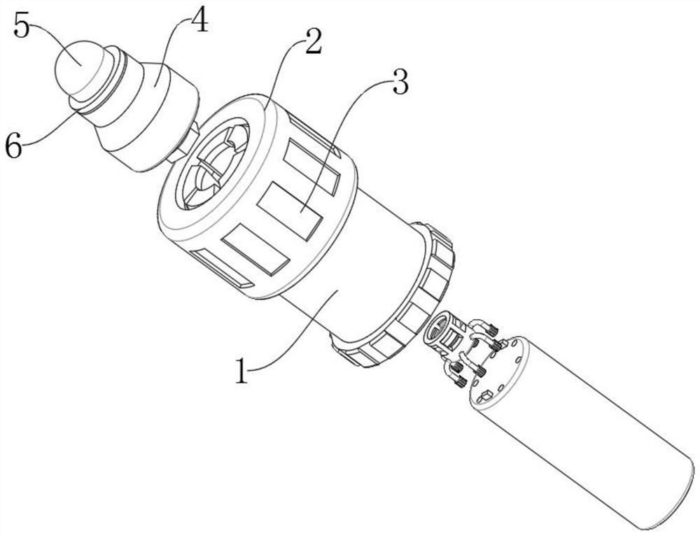
[0028] Example 1, as Figure 1-6 As shown, the present invention provides a technical solution for an auxiliary device for orthopedic arthroscopic surgery: it includes a fixing sleeve body 1, the top of the fixing sleeve body 1 is fixed with a plurality of arc-shaped spring sheets 12 equidistantly along the circumferential direction, and the outer surface of the fixing sleeve body 1 is fixed at equal intervals. A threaded groove 14 is opened on the surface near the top edge, the outer surface of the fixed sleeve body 1 is fitted with a locking sleeve 2 near the top edge, and a thread 13 is provided between the inner walls of the locking sleeve 2 near the bottom edge. 13 is engaged with the inside of the threaded groove 14 , and a bevel 18 is defined between the inner walls of the locking sleeve 2 near the top edge.

[0029] The effect achieved by the entire embodiment 1 is that when using the device, first put the arthroscope 5 together with the connecting block 7 and the clam...

Embodiment 2

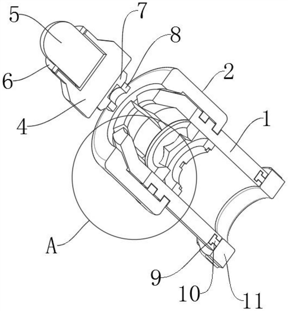
[0030] Example 2, as Figure 1-6 As shown, the bottom of the fixed sleeve body 1 is provided with an annular groove 9, the inner part of the annular groove 9 is rotatably connected with an annular block 10, the bottom of the annular block 10 is provided with a connecting sleeve 11, and the outer surface of the connecting sleeve 11 is locked in the circumferential direction and locked The outer surface of the sleeve 2 is equally spaced with a plurality of anti-skid lines 3 along the circumferential direction. A support ring 15 is fixed between the inner walls of the fixed sleeve body 1 near the top edge. The top of the support ring 15 is provided with a tapered groove 17. The inner bottom surface of the slot 17 is provided with a clamping slot 16, and a docking seat 4 is arranged between the inner walls of the four arc-shaped spring sheets 12. The top of the docking seat 4 is fixed with the arthroscope 5, and the bottom of the docking seat 4 is fixed with a connecting block 7. ...

Embodiment 3

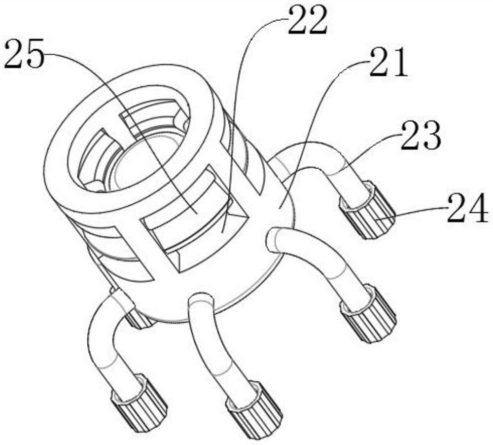
[0032] Example 3, as Figure 1-6As shown, a limit ring 19 is fixed in the middle between the inner walls of the fixed sleeve body 1, and a plurality of limit grooves 20 are equally spaced at the bottom of the upper limit ring 19 along the circumferential direction. Both are engaged with the limit blocks 29 , a rubber column 28 is fixed between one side of the two limit blocks 29 , the rubber columns 28 are engaged with the inside of the fixing sleeve body 1 , and the outer surface of the rubber column 28 is connected to the inner wall of the connecting sleeve 11 . A plurality of mounting holes 30 are formed on one side of the rubber column 28 equidistantly along the circumferential direction, and the plurality of mounting holes 30 all penetrate to the other side of the rubber column 28, and the interior of the clamping block 8 is slidably connected with a pair of joints 21, the outer surface of the joint 21 is provided with a plurality of side ports 22 at equal distances in th...


PUM


Abstract

The invention provides an orthopaedic arthroscopic surgery auxiliary device, and relates to the technical field of arthroscopes, the orthopaedic arthroscopic surgery auxiliary device comprises a fixing sleeve body, a plurality of arc-shaped spring pieces are fixed to the top of the fixing sleeve body at equal intervals in the circumferential direction, and a threaded groove is formed in the position, close to the top edge, of the outer surface of the fixing sleeve body; the arthroscope fixing sleeve comprises a fixing sleeve body, the position, close to the top edge, of the outer surface of the fixing sleeve body is sleeved with a locking sleeve, and the position, close to the bottom edge, between the inner walls of the locking sleeve is provided with a thread line. According to the arthroscope fixing device, the locking sleeve is arranged on the locking sleeve, so that the locking sleeve is supported and positioned, threaded connection is firmer, and the problems that when the arthroscope is fixed, the arthroscope is fixed to the butt joint position mostly through threaded connection, but when the arthroscope is subjected to force opposite to the thread line direction, the arthroscope is likely to fall off, and troubles are brought to people in use are solved.

Description

technical field [0001] The invention relates to the technical field of arthroscopy, in particular to an auxiliary device for orthopedic arthroscopy. Background technique [0002] Arthroscope is a rod-shaped optical instrument with a diameter of about 5mm for observing the internal structure of a joint, and it is an endoscope for the diagnosis and treatment of joint diseases. Arthroscopes have a lens at the end of a thin tube that is inserted into the joint and the structure inside the joint is displayed on a monitor. Therefore, the structure inside the joint can be directly observed. Arthroscopy is not only used for the diagnosis of diseases, but also has been widely used for the treatment of joint diseases. [0003] At present, when fixing the arthroscope, the arthroscope is mostly fixed in the docking position by screw connection, but when the force opposite to the thread direction is applied, the arthroscope can easily fall off, which brings trouble to people's use. S...

Claims


Application Information

Patent Timeline
Patent Type & Authority Applications(China)
IPC IPC(8): A61B1/317A61B1/00A61B17/00
CPCA61B1/317A61B1/00147A61B17/00234A61B2017/00238
Inventor 楚亚杰张会选
Owner 楚亚杰
Why Eureka
Try Eureka