
Gynecological obstetric forceps

A gynecological and clamping technology, applied in the field of gynecological surgery, can solve the problems of affecting the traction operation, easy to take off, and pulling the baby's neck with excessive force, so as to ensure the safety of traction, avoid safety accidents, and improve the safety and efficiency of midwifery. Effect

Inactive Publication Date: 2022-06-07
陈凤丽
View PDF0 Cites 0 Cited by
  • Summary
  • Abstract
  • Description
  • Claims
  • Application Information

AI Technical Summary

Problems solved by technology

[0004] Aiming at the deficiencies in the prior art, the object of the present invention is to provide a gynecological forceps that can lock the clamping force to prevent it from being separated from the secondary clamping, and can conveniently observe the pulling force to ensure that the baby will not be injured, so as to solve the problem of the existing forceps During the process of clamping the fetus and giving birth, the clamping force cannot be locked, resulting in the need to share a large proportion of clamping during the clamping and traction process, which is unfavorable for long-term traction midwifery work, and it is easy to lose force or affect the midwifery. For traction operation, the clamping force is mostly controllable at present, but the pulling force is uncontrollable. There are still phenomena such as baby’s neck injury and ear breakage due to excessive pulling force. The fetal head is clamped again, which slows down the labor process.

Method used


Image

  • Gynecological obstetric forceps
  • Gynecological obstetric forceps
  • Gynecological obstetric forceps

Examples


Embodiment Construction

[0021] In order to make the technical means, creative features, achievement goals and effects realized by the present invention easy to understand, the present invention will be further described below with reference to the specific embodiments.

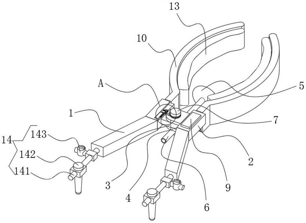
[0022] see figure 1 , figure 1 It is a schematic diagram of the three-dimensional structure of the present invention.

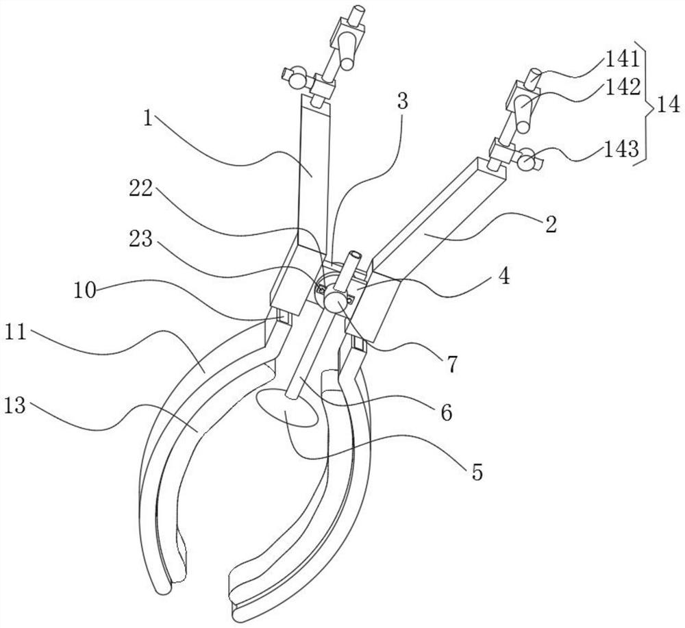
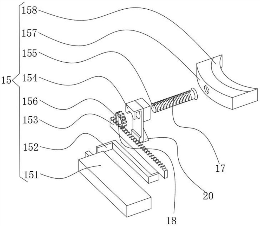
[0023] A gynecological forceps, comprising a connecting handle 1, a connecting handle 2 2, a connecting block 1 3, a connecting block 2 4, a suction cup 5 and a suction tube 6, the connecting block 1 3 is fixedly connected to one side of the connecting handle 1, the connecting block 2 4 is fixedly connected to one side of the connecting handle two 2, the connecting block one 3 is provided with a connecting shaft 7, a suction cup 5, the connecting block one 3 is movably connected with the connecting block two 4 through the connecting shaft 7, and the connecting handle one 1 and the connecting handle two A tension s...


PUM


Abstract

The obstetric forceps comprise a first connecting handle, a second connecting handle, a first connecting block, a second connecting block, a suction cup and a suction pipe, and the first connecting block is fixedly connected to one side of the first connecting handle. According to the obstetric forceps, clamping force can be locked and prevented from being separated from secondary clamping, pulling force can be conveniently observed, it is guaranteed that a baby cannot be pulled, and the problems that in the process that the baby is delivered through existing obstetric forceps, the clamping force cannot be locked, a large proportion needs to be shared for tight holding in the clamping and traction process, and the labor intensity is high are solved. For long-time traction midwifery work is unfavorable, force is easy to fall off or traction operation of midwifery doctors is affected, at present, most clamping force is controllable, but pulling traction force is uncontrollable, the phenomena that the neck of a baby is injured, the ears are broken and the like due to too large pulling force still exist, and when force is not applied to a pair of obstetric forceps, the obstetric forceps are easy to separate from the head of a fetus. The head of the fetus needs to be clamped again, and the delivery process is slowed down.

Description

technical field [0001] The invention relates to the technical field of gynecological surgery, in particular to a gynecological forceps. Background technique [0002] Gynecological forceps is an instrument that can be used to assist mothers in delivering the fetus. Specifically, the head of the fetus is clamped by the forceps, and the head of the fetus is pulled to move outside the uterus of the mother, shortening the labor process and terminating the pregnancy as soon as possible, so as to reduce the pain of the mother and reduce the risk of pregnancy. Ensure the safety of the fetus. Forceps are one of the important means to solve the fetal head dystocia and improve the neonatal survival rate. [0003] However, the traditional forceps structure is simple, and the fetus is easily pinched during the delivery of forceps, causing various complications in the newborn, such as brachial plexus injury, clavicle fracture, forceps scars, facial skin rupture, and neonatal asphyxia. I...

Claims


Application Information

Patent Timeline
IPC IPC(8): A61B17/44
CPCA61B17/44A61B2017/445
Inventor 陈凤丽
Owner 陈凤丽
Learn More