Visual positioning method and device based on two-dimensional code and computer readable storage medium
A visual positioning and two-dimensional code technology, applied in manipulators, program-controlled manipulators, manufacturing tools, etc., can solve problems such as large visual positioning errors, and achieve the effects of improving accuracy, reducing labor costs, and speeding up production rhythm.
- Summary
- Abstract
- Description
- Claims
- Application Information
AI Technical Summary
Problems solved by technology
Method used
Image

Examples
Embodiment 1
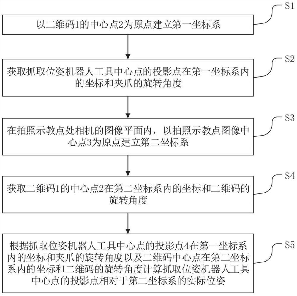
[0044] figure 1 It is a flowchart of the visual positioning method based on two-dimensional code in the first embodiment of the present invention, such as figure 1 As shown, the present embodiment provides a two-dimensional code-based visual positioning method, the steps of which include:
[0045] S1. Establish a first coordinate system with the center point 2 of the two-dimensional code 1 as the origin;
[0046] S2, obtain the coordinates of the projection point of the center point of the grasping pose robot tool in the first coordinate system and the rotation angle of the gripper;
[0047] S3. In the image plane of the camera at the photographing and teaching point, a second coordinate system is established with the image center point 3 of the photographing and teaching point as the origin;
[0048] S4, obtain the coordinates of the center point 2 of the two-dimensional code 1 in the second coordinate system and the rotation angle of the two-dimensional code;
[0049] S5....
Embodiment 2
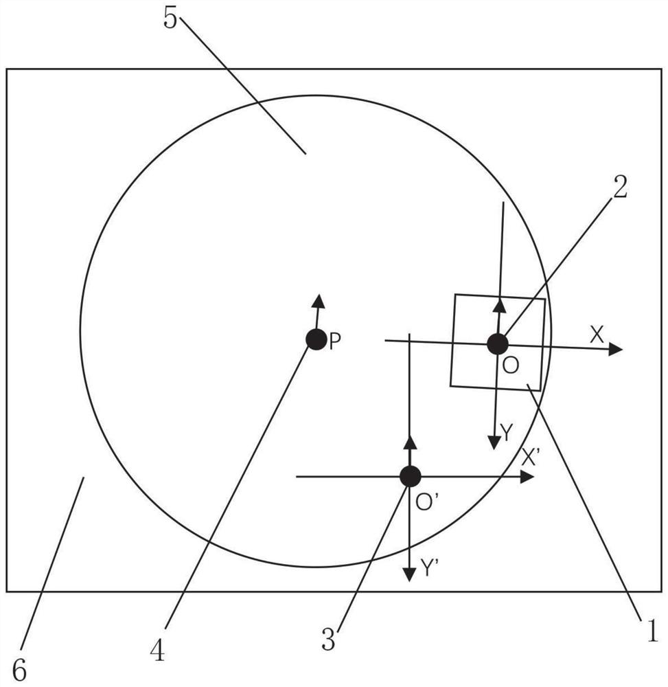
[0052] figure 2 It is a schematic diagram of the positional relationship between the origin of the first coordinate system, the origin of the second coordinate system and the projection point of the center point of the grasping pose robot tool in the second embodiment of the present invention, as shown in figure 2 As shown in this embodiment, preferably, the process of establishing the first coordinate system in S1 is as follows: take the center point of the two-dimensional code as the origin O of the coordinate system, the rightward direction of the two-dimensional code is the X-axis, and the downward direction of the two-dimensional code For the Y axis, establish a plane rectangular coordinate system XOY, that is, the first coordinate system.
[0053] In S2, measure the coordinates (x 0 , y 0 ) and the angle of rotation of the gripper 0 .
[0054] The process of establishing the second coordinate system in S3 is: in the image plane of the camera at the photographing an...
Embodiment 3
[0075] The difference between this embodiment and the first embodiment is that:
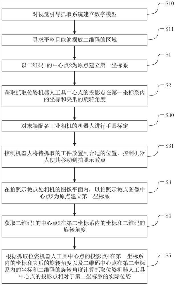
[0076] image 3 is the flow chart of the two-dimensional code-based visual positioning method in the third embodiment of the present invention; such as image 3 As shown, before executing S1, perform the following steps:
[0077] S10, establishing a digital model for the vision-guided grasping system;
[0078] S11. Seek a flat area where the QR code can be placed;
[0079] Preferably this area is a rectangular area 6 .
[0080] Vision-guided grasping systems include workpieces, robots, and fixtures, among others.
[0081] In addition, before executing S3, perform the following steps:
[0082] S30. Perform hand-eye calibration on a robot equipped with an industrial camera at the end;
[0083] S31 , the robot is controlled to place the workpiece to be grasped at a suitable position, and the robot is controlled to move to the photographing and teaching point.
PUM
 Abstract
Description
Claims
Application Information
 - R&D Engineer
- R&D Manager
- IP Professional
- Industry Leading Data Capabilities
- Powerful AI technology
- Patent DNA Extraction
Browse by: Latest US Patents, China's latest patents, Technical Efficacy Thesaurus, Application Domain, Technology Topic.
© 2024 PatSnap. All rights reserved.Legal|Privacy policy|Modern Slavery Act Transparency Statement|Sitemap