
Control method and device of unmanned equipment

A control method and equipment technology, applied in the computer field, capable of solving problems such as collisions

Pending Publication Date: 2022-06-07
BEIJING SANKUAI ONLINE TECH CO LTD
View PDF0 Cites 0 Cited by
  • Summary
  • Abstract
  • Description
  • Claims
  • Application Information

AI Technical Summary

Problems solved by technology

At this time, if the incoming vehicle is blocked by obstacles in this area (that is, the incoming vehicle is located in a blind spot that the unmanned equipment cannot perceive), the unmanned equipment will not be able to perceive the existence of the incoming vehicle, and may danger of collision

Method used


Image

  • Control method and device of unmanned equipment
  • Control method and device of unmanned equipment
  • Control method and device of unmanned equipment

Examples


Embodiment Construction

[0047]In order to make the purpose, technical solutions and advantages of this specification clearer, the technical solutions of this specification will be clearly and completely described below in conjunction with specific embodiments of this specification and the corresponding drawings. Obviously, the described embodiments are only some of the embodiments of the present specification, but not all of the embodiments. Based on the embodiments in this specification, all other embodiments obtained by persons of ordinary skill in the art without creative efforts shall fall within the protection scope of this specification.

[0048] The control scheme of the unmanned equipment provided in this specification will be described in detail below with reference to the embodiments.

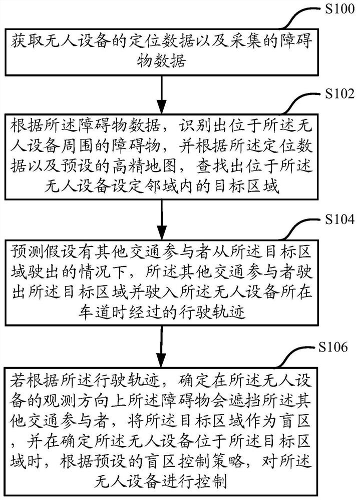
[0049] figure 1 This is a schematic flowchart of a control method for an unmanned device in this specification, which specifically includes the following steps:

[0050] In step S100, the positioning data ...


PUM


Abstract

The invention discloses a control method and device for unmanned equipment, and particularly discloses a method for obtaining positioning data of the unmanned equipment and collected obstacle data, recognizing obstacles located around the unmanned equipment according to the obstacle data, and determining the position of the unmanned equipment according to the positioning data and a preset high-precision map. The method comprises the following steps: searching a target area in a set neighborhood of unmanned equipment, predicting a driving track of other traffic participants when the other traffic participants drive out of the target area and drive into a lane where the unmanned equipment is located under the assumption that the other traffic participants drive out of the target area, and if the other traffic participants drive out of the target area and drive into the lane where the unmanned equipment is located, determining that the unmanned equipment passes through the driving track. And determining that the obstacle can shield other traffic participants in the observation direction of the unmanned equipment, taking the target area as a blind area, and when determining that the unmanned equipment is located in the target area, controlling the unmanned equipment according to a preset blind area control strategy. Therefore, the labor cost is reduced, meanwhile, the blind area is found in time, and the safety risk in the driving process of the unmanned equipment is reduced.

Description

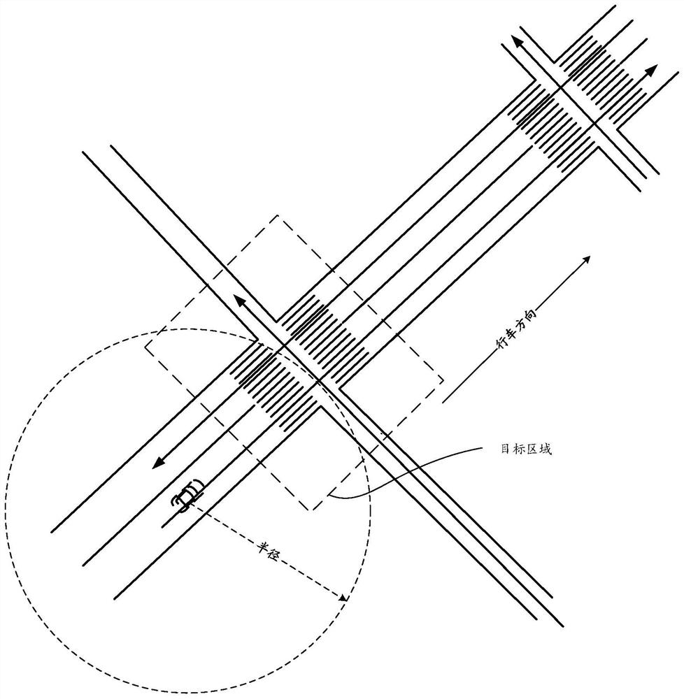
technical field [0001] This specification relates to the field of computer technology, and in particular, to a control method and device for unmanned equipment. Background technique [0002] In the process of automatic driving of unmanned equipment, when unmanned equipment passes through areas where roads intersect, such as school gates, residential gates, etc., there will be vehicles entering. At this time, if the merging vehicle in this area is blocked by an obstacle (that is, the merging vehicle is located in a blind spot that the unmanned equipment cannot perceive), the unmanned equipment will not be able to perceive the existence of the merging vehicle, which may cause Danger of collision, etc. Therefore, for these areas, full-time personnel usually go to these areas to manually measure and map the size of the blind areas that unmanned equipment cannot perceive, and mark them on the high-precision map. In this way, when the unmanned device determines that there is an ...

Claims


Application Information

Patent Timeline
IPC IPC(8): B60W30/09B60W30/08G01S13/931B60W60/00
CPCB60W30/09B60W30/08G01S13/931B60W60/0027B60W60/0016B60W60/0017
Inventor 张健珲丁文玲刘宇达符宗恺虞航仲杨磊夏华夏
Owner BEIJING SANKUAI ONLINE TECH CO LTD
Learn More