Safety protection device for building construction
A safety protection device and construction technology, which is applied in the direction of construction, building structure, scaffolding accessories, etc., can solve the problems of inconvenient construction personnel to solve internal emergencies, and achieve the effect of being convenient for free mobile construction and high-altitude operations
- Summary
- Abstract
- Description
- Claims
- Application Information
AI Technical Summary
Problems solved by technology
Method used
Image
Examples
Embodiment 1
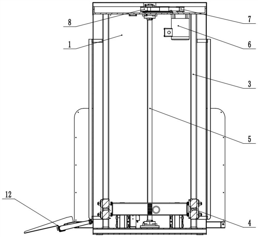
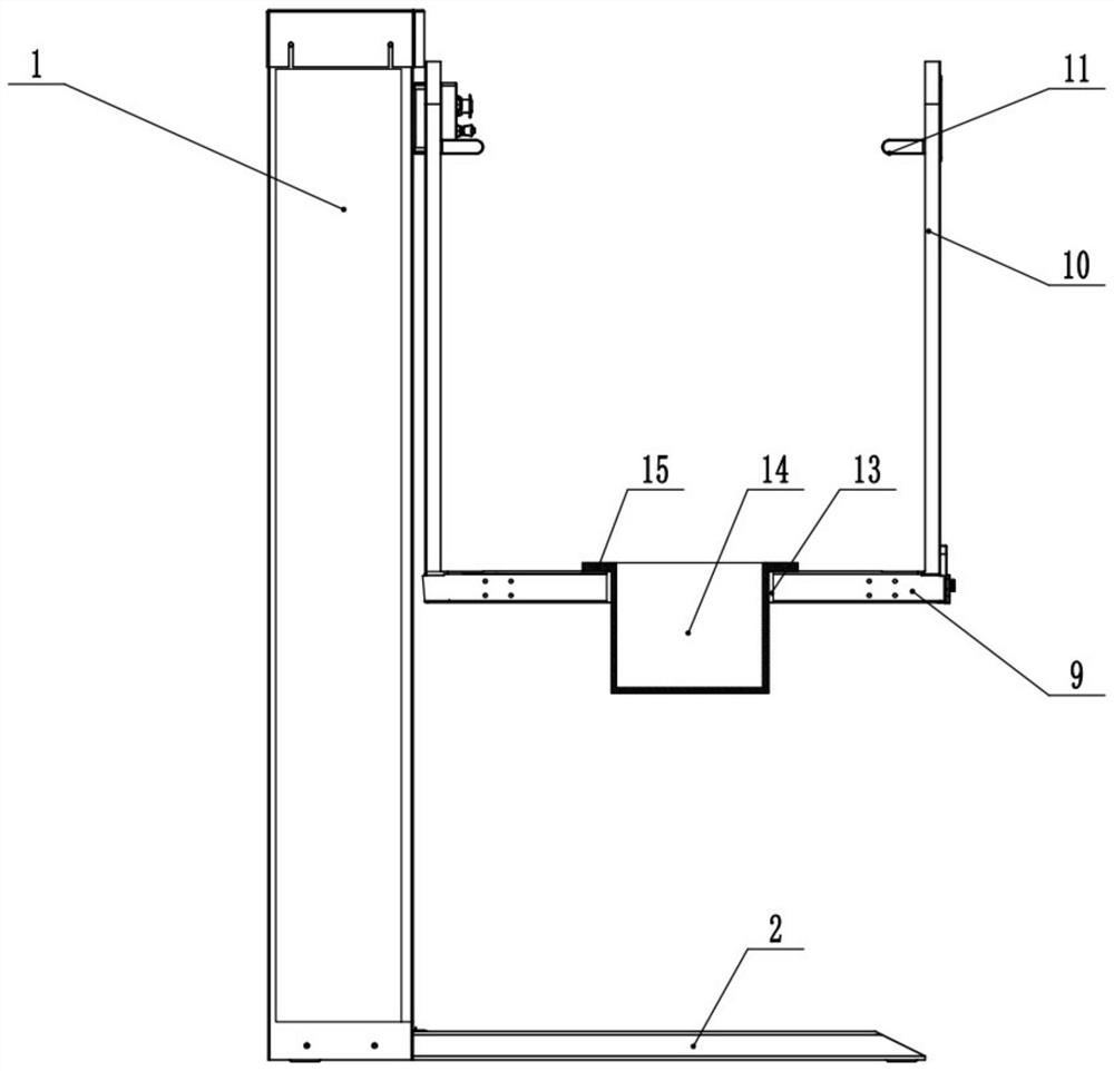
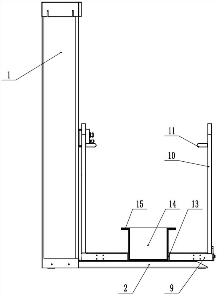
[0038] like figure 1As shown, a construction safety protection device includes a work box 1, and a bottom plate 2 is welded and fixed on the side wall of the work box 1 near the bottom. The right side of the work box 1 is an open structure. Two guide rails 3 parallel to each other are vertically welded and fixed inside the work box 1 . A sliding seat 4 is vertically slid on the two guide rails 3 . There is also a lead screw 5 between the two guide rails 3 , the lead screw 5 is vertically rotatably connected to the inner wall of the work box 1 , and the central axis of the lead screw 5 is parallel to the central axis of the guide rail 3 . A ball seat is welded and fixed on the sliding seat 4 , and the ball seat and the screw 5 cooperate with each other to form the ball screw 5 . The top of the lead screw 5 is connected and fixed with a first transmission wheel 7 by a coaxial key. The inner vertical bolt of the working box 1 is fixed with a servo motor 6 . The central axis of...
specific Embodiment approach
[0041] The specific implementation is as follows: the construction personnel first control the rotation of the servo motor 6, and use the transmission of the first transmission wheel 7 to drive the second transmission wheel 8 and the lead screw 5 to rotate. During the rotation of the lead screw 5, the sliding seat 4 is driven to move downward along the guide rail 3 until the bearing plate 9 moves to the lowest end. When the carrying plate 9 moves to the lowest end, the construction personnel press down the guide plate 12 to the ground, thereby facilitating access to the carrying plate 9 .
[0042] When the construction personnel enter the carrying plate 9, the servo motor 6 is controlled to rotate to make the carrying plate 9 rise. During the rising process of the carrying plate 9 , the accommodating box 14 slides downward under the action of gravity until the supporting plate 15 collides with the carrying plate 9 . When the construction personnel work at high altitudes on th...
Embodiment 2
[0045] The difference between this embodiment and the first embodiment is that, as shown in the appendix Figure 4 with attached Figure 5 As shown, the left side wall of the accommodating box 14 is welded and fixed with the second rack 18 . The left side of the working box 1 is also vertically fixed with a support table by welding, and a first rack 17 is vertically fixed on the left side of the support table. A cavity 16 is opened inside the carrier plate 9, and the left and right ends of the cavity 16 communicate with the outside. A first gear 19 is rotatably connected in the cavity 16 , and the left side of the first gear 19 meshes with the first rack 17 . A first sprocket gear and a second sprocket gear are respectively rotatably connected in the cavity 16 , and a tooth chain is fitted between the first sprocket gear and the second sprocket gear. The first sprocket is coaxially and fixedly connected with the third gear 21 , and the first gear 19 is engaged with the left...
PUM
 Abstract
Description
Claims
Application Information
 - R&D
- Intellectual Property
- Life Sciences
- Materials
- Tech Scout
- Unparalleled Data Quality
- Higher Quality Content
- 60% Fewer Hallucinations
Browse by: Latest US Patents, China's latest patents, Technical Efficacy Thesaurus, Application Domain, Technology Topic, Popular Technical Reports.
© 2025 PatSnap. All rights reserved.Legal|Privacy policy|Modern Slavery Act Transparency Statement|Sitemap|About US| Contact US: help@patsnap.com


