Lifting platform for conveying building materials

A technology for building materials and lifting platforms, applied in the field of lifting platforms, can solve problems such as adjusting the lifting platform and reducing work efficiency, and achieve the effects of preventing shaking, improving work efficiency, and preventing falling

Pending Publication Date: 2022-08-09
朱智才
View PDF1 Cites 1 Cited by
  • Summary
  • Abstract
  • Description
  • Claims
  • Application Information

AI Technical Summary

Problems solved by technology

[0005] In order to overcome the shortcomings of the construction material lifting platform that cannot adjust the lifting platform according to the higher working height, thereby reducing the work efficiency

Method used


Image

  • Lifting platform for conveying building materials
  • Lifting platform for conveying building materials
  • Lifting platform for conveying building materials

Examples


Example Embodiment

[0042] Example 1

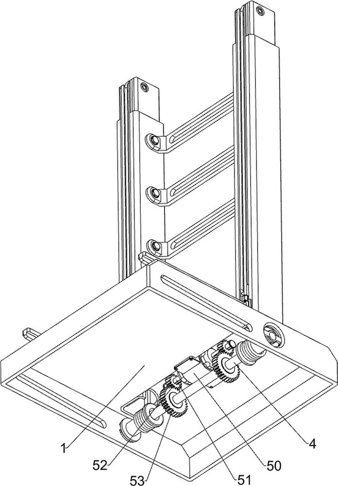
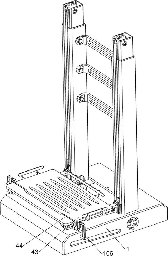
[0043] A construction material conveying lifting platform, such as Figure 1-10As shown, it includes a base 1, a support plate 2, a sliding plate 3, a first rotating shaft 4, a pulling rope 41, a reel 42, a placing rack 43, a first rotating plate 44, a rotating mechanism 5 and a clamping mechanism 6, the base 1. There is a support plate 2 at the rear of the upper side, and the left and right sides of the support plate 2 are slidably connected with a sliding plate 3. The left and right sides of the base 1 are rotatably connected with a first shaft 4. A placing rack 43 is slidably connected between the two. The placing rack 43 can be used to place building materials. Both the left and right sides of the upper part of the sliding plate 3 are rotatably connected with reels 42. The reel 42, the upper reel 42 is wound with a pulling rope 41, one end of the pulling rope 41 is connected to the upper side of the placing frame 43, and the other end of the pulling rop...

Example Embodiment

[0047] Example 2

[0048] On the basis of Example 1, as figure 1 , figure 2 , image 3 , Figure 11 and Figure 12 As shown, it also includes a buffer mechanism 7 capable of buffering the placement rack 43. The buffer mechanism 7 includes a first fixing block 70, a second sliding rod 71, a connecting block 72 and a second spring 73. The upper left and right sides of the sliding plate 3 Each side is provided with a first fixing block 70 , a second sliding rod 71 is slidably connected to the first fixing block 70 , a connecting block 72 is provided between two adjacent second sliding rods 71 ​​, and the upper side of the connecting block 72 is A second spring 73 is provided between the lower side of the first fixing block 70 and the second spring 73 is wound on the surface of the second sliding rod 71 . act as a buffer.

[0049] When people transport building materials for high-altitude operations, they first place the building materials on the placement rack 43, and then...


PUM


Abstract

The invention relates to a lifting table, in particular to a building material conveying lifting table. According to the building material conveying lifting table, the lifting table can be adjusted according to higher-place operation, and then the working efficiency is improved. A building material conveying lifting platform comprises a base, a supporting plate, sliding plates, a first rotating shaft and the like, the supporting plate is arranged on the rear portion of the upper side of the base, the sliding plates are arranged on the left side and the right side of the supporting plate in a sliding mode, and the first rotating shaft is rotationally arranged between the left side and the right side of the base. A clamping rod is pulled outwards, so that a sliding plate moves upwards, then a double-shaft motor is started, an output shaft of the double-shaft motor rotates to drive a first gear to rotate, then a winding wheel rotates, a pull rope is wound, then a placing frame slides upwards, people can conveniently conduct high-place operation, and the working efficiency can be improved.

Description

technical field [0001] The invention relates to a lifting platform, in particular to a building material conveying lifting platform. Background technique [0002] Building materials are a general term for materials used in civil engineering and construction projects. In the process of building construction, building materials often need to be transported to high places for operation. When transporting building materials to high places, lifting platforms are usually used for transportation. During the transportation of building materials, people are often required to guard on the lifting platform, thereby reducing work efficiency. [0003] The application patent number is CN202020856364.0 A lifting platform for building materials, including a lifting platform, the bottom of the lifting platform is provided with a telescopic rod for adjusting the height of the lifting platform, and two side walls of the lifting platform are slidingly provided with vertical moving rods. baffle...

Claims


Application Information

Patent Timeline
IPC IPC(8): B66F7/02B66F7/28
CPCB66F7/02B66F7/28
Inventor 朱智才
Owner 朱智才
Why Eureka
Try Eureka