Combustion chamber structure of internal combustion engine

A combustion chamber and internal combustion engine technology, applied to internal combustion piston engines, combustion engines, mechanical equipment, etc., can solve problems such as abnormal ignition, lack of cylinders in internal combustion engines, and ineffective release of energy

Pending Publication Date: 2022-06-07
朱炫 +1
View PDF0 Cites 2 Cited by
  • Summary
  • Abstract
  • Description
  • Claims
  • Application Information

AI Technical Summary

Problems solved by technology

However, since the fuel gas is ignited by the ignition end in the pre-combustion chamber, the force generated after the fuel gas is scattered and linearly acts on the inner wall surface of the choke shell surrounding the pre-chamber, and generates expansion pressure on the inner wall surface of the choke shell, and the choke The larger the area and number of through holes or channels on the shell wall, the smaller the force generated after the fuel gas is ignited at the ignition end, and the smaller the expansion pressure generated in the pre-combustion chamber, thus affecting the jet flow in the pre-combustion chamber into the main chamber. The speed of flame propagation in the combustion chamber
Although the smaller the through hole, the expansion pressure generated after the fuel gas is ignited in the pre-combustion chamber will increase, and the injection speed will also become faster, but the smaller the through hole, on the one hand, the fuel gas entering the pre-combustion chamber will be relatively reduced. , so it will cause the problem of insufficient supply of fuel gas in the pre-combustion chamber, resulting in abnormal ignition, lack of cylinders or non-working phenomena of the internal combustion engine, resulting in reduced efficiency or unstable operation of the internal combustion engine; The gas flow rate of the combustion chamber is also reduced accordingly, resulting in that the energy generated by the combustion in the pre-combustion chamber cannot be effectively released to the main combustion chamber to ignite the fuel gas in the main combustion chamber, resulting in energy loss in the pre-combustion chamber

Method used


Image

  • Combustion chamber structure of internal combustion engine
  • Combustion chamber structure of internal combustion engine
  • Combustion chamber structure of internal combustion engine

Examples


Embodiment 1

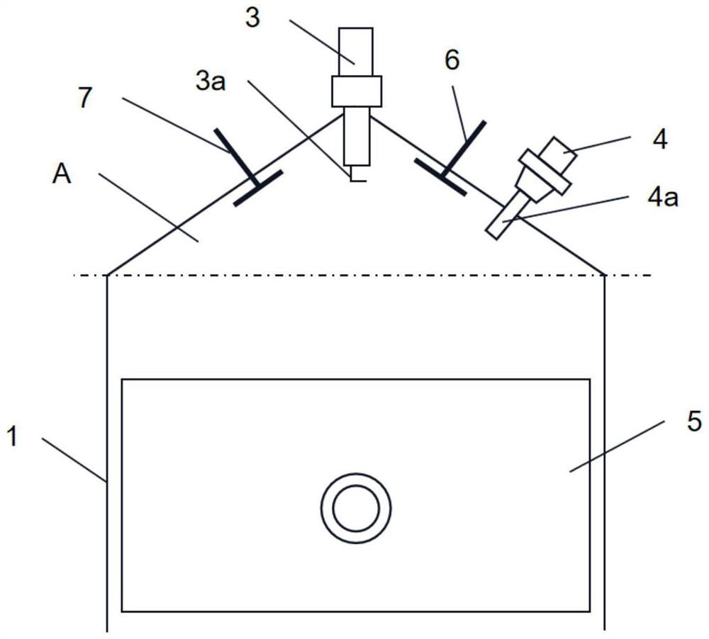
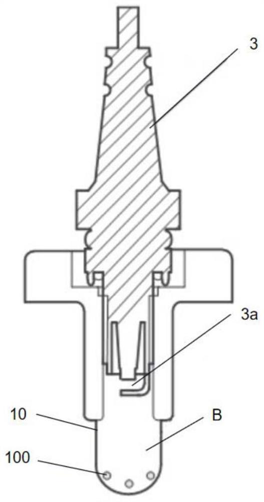
[0045] see image 3 , image 3 It is a partial cross-sectional view of the combustion chamber structure in Embodiment 1 of the present invention. Depend on image 3 It can be seen that the combustion chamber structure of the internal combustion engine includes a combustion chamber (not shown), an ignition device (not shown) and a choke casing 10, the combustion chamber is a closed cavity, and the ignition end 3a of the ignition device extends into the inside the combustion chamber. The choke casing 10 is located in the combustion chamber and surrounds the ignition end 3a of the ignition device to form a pre-combustion chamber B, and a main combustion chamber A is formed between the choke casing 10 and the inner wall of the combustion chamber. In this embodiment, the choke casing 10 is a circular arc surface that protrudes away from the ignition end 3a. The choke casing 10 is provided with a guide hole 110 for connecting the pre-combustion chamber B and the main combustion ...

Embodiment 2

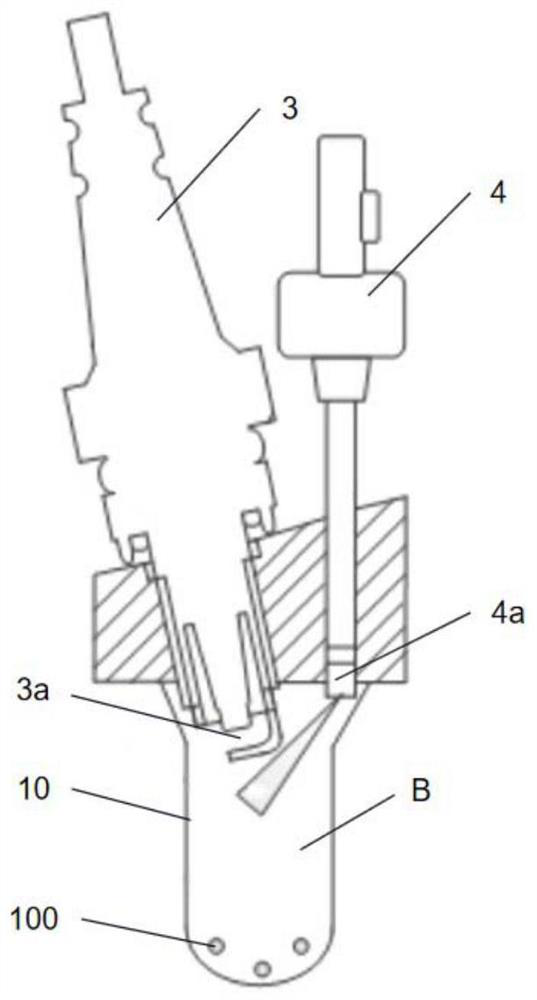
[0048] see Figure 4 , Figure 4 It is a partial cross-sectional view of the combustion chamber structure in Embodiment 2 of the present invention. Depend on Figure 4 It can be seen that the combustion chamber structure of the internal combustion engine includes a combustion chamber (not shown), an ignition device (not shown) and a choke casing 10, the combustion chamber is a closed cavity, and the ignition end 3a of the ignition device extends into the inside the combustion chamber. The choke casing 10 is located in the combustion chamber and surrounds the ignition end 3a of the ignition device to form a pre-combustion chamber B, and a main combustion chamber A is formed between the choke casing 10 and the inner wall of the combustion chamber. In this embodiment, the choke casing 10 is a circular arc surface that protrudes away from the ignition end 3a. A slit (not shown) is provided on the position where any extension surface D extends to the choke case 10, and the slit...

Embodiment 3

[0051] Please refer to FIG. 5 , FIG. 5( a ) is a top view of the combustion chamber structure in Embodiment 3 of the present invention, and FIG. 5( b ) is a longitudinal cross-sectional view of the combustion chamber structure in Embodiment 3 of the present invention. Depend on Figure 5(a) and 5(b) It can be seen that the choke casing 10 is a circular arc surface that protrudes away from the ignition end 3a. The difference between the combustion chamber structure of this embodiment and the combustion chamber structure of Embodiment 2 is that the baffle shell of this embodiment is provided with three flow guide holes.

[0052] combine Figure 5(a) and 5(b) , the first extension surface D1, the second extension surface D2 and the third extension surface D3 that intersect on the same intersection line C extend to the position of the choke case 10, and are respectively provided with a cutout (not shown in the figure), each cutout is at The choke case 10 is respectively formed...


PUM


Abstract

The invention relates to an internal combustion engine combustion chamber structure which comprises a combustion cavity, an ignition device and a flow choking shell, the combustion cavity is a closed cavity, the ignition end of the ignition device extends into the combustion cavity, and the flow choking shell is located in the combustion cavity and surrounds the ignition end to form a pre-combustion chamber. A main combustion chamber is formed between the flow choking shell and the inner wall of the combustion cavity, the flow choking shell is provided with at least one flow guide hole communicated with the pre-combustion chamber and the main combustion chamber, and the connecting line of the ignition end and any point of the flow guide hole is blocked. The device is ingenious in design, simple in structure, easy to manufacture, high in applicability and low in cost.

Description

technical field [0001] The invention relates to the technical field of internal combustion engines, in particular to a combustion chamber structure of an internal combustion engine. Background technique [0002] The internal combustion engine is a kind of heat engine that converts thermal energy into mechanical energy after mixing liquid or gas fuel with air, and directly inputting it into the high-pressure combustion chamber inside the cylinder to burn and explode to generate power. see figure 1 , a conventional internal combustion engine includes a cylinder block 1, a cylinder head 2, an ignition device 3 (spark plug), an injector 4, a piston 5, an intake valve 6 and an exhaust valve 7. The cylinder block 1 and the cylinder head 2 enclose a main combustion chamber cavity A; the ignition device 3 and the fuel injector 4 are arranged on the top of the gas cylinder 1, and the ignition end 3a of the ignition device 3 and the nozzle 4a of the fuel injector 4 into the combusti...

Claims


Application Information

Patent Timeline
Patent Type & Authority Applications(China)
IPC IPC(8): F02B19/18F02B19/12
CPCF02B19/18F02B19/12Y02T10/12
Inventor 朱炫
Owner 朱炫
Why Eureka
Try Eureka