Auxiliary device for laying power transmission line

A technology for power transmission lines and auxiliary devices, which is applied in the directions of transportation and packaging, thin material handling, and transportation of filamentous materials. Cable crimping and other problems, to avoid the phenomenon of winding and knotting, to facilitate lifting and transportation, and to ensure the effect of stability

Pending Publication Date: 2022-06-17
国网河南省电力公司栾川县供电公司 +1
View PDF0 Cites 0 Cited by
  • Summary
  • Abstract
  • Description
  • Claims
  • Application Information

AI Technical Summary

Problems solved by technology

[0004] 1. In order to ensure the safety of cable transportation, the cable reel is often placed vertically during transportation. When the subsequent lifting equipment lifts the cable reel to the ground, it is usually also a vertical hoisting line to ensure the stability of the lifting. The cable reel is placed on the ground, and the staff needs to manually move the cable reel later. For the cable reel wrapped with large-diameter cables, the weight of the cable reel is relatively large, and manual movement is time-consuming and laborious;
[0005] 2. The existing cable reel support usually supports the cable reel horizontally for rotation, an

Method used


Image

  • Auxiliary device for laying power transmission line
  • Auxiliary device for laying power transmission line
  • Auxiliary device for laying power transmission line

Examples


Embodiment 1

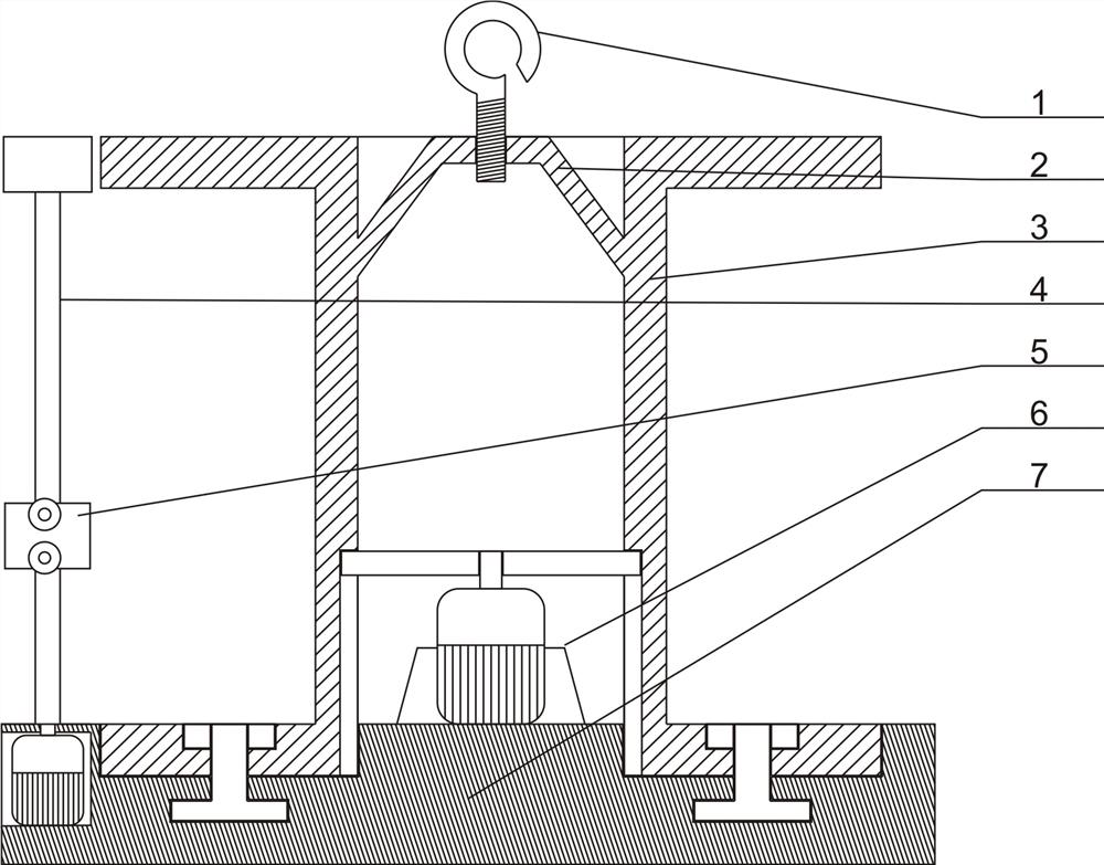
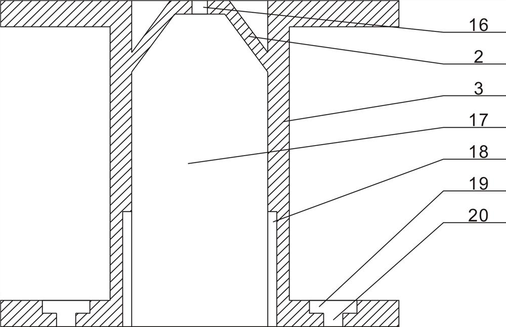
[0039]Embodiment 1, an auxiliary device for laying power transmission lines, including a base 7 and a cable reel 3, the upper surface of the base 7 is provided with an annular groove 12, and several inner bottom surfaces of the annular groove 12 are evenly distributed to support the cable reel 3, And realize the rolling member 13 that the cable reel 3 rotates, the rolling member 13 is a universal ball or a rolling shaft that is consistent with the direction of rotation of the cable reel 3, and the vertically placed cable reel 3 is placed in the annular groove 12 on the base 7 , the middle part of the vertically placed cable reel 3 forms a columnar inner cavity 17, the upper and lower ends of the columnar inner cavity 17 are open structures, the upper part of the columnar inner cavity 17 is provided with a lifting frame 2, and the upper part of the lifting frame 2 is provided with mounting screw holes 16, The hook 1 is threadedly connected with the mounting screw hole 16. Throug...

Embodiment 2

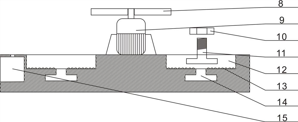
[0043] Embodiment 2, for the winding or unwinding operation of a large-diameter cable, due to its heavy mass, the inertia of the cable reel 3 during the rotation is relatively large. The inner bottom surface of the annular groove 12 is provided with a bottom annular groove 14. The cross section of the bottom annular groove 14 is an inverted T-shaped structure. The bottom annular groove 14 is provided with a bolt 11 that slides along the bottom annular groove 14. The vertically placed The bottom side plate of the cable reel 3 is provided with a limit hole 20 that is compatible with the bolt 11. The head of the bolt 11 penetrates the limit hole 20 and is fixed by a nut 10. In order to ensure the flatness of the bottom side plate of the cable reel 3 A sinking groove 19 is provided on the bottom side plate of the cable tray 3 , and the limiting hole 20 is arranged on the inner bottom surface of the sinking groove 19 .

Embodiment 3

[0044] Embodiment 3, since the cables on the cable reel 3 are helically reciprocated, the cable combing mechanism 5 also needs to carry out reciprocating lifting motions. Automatic lifting drive, the upper end of the vertical rod 4 is provided with a top plate 21, the upper end of the screw rod 23 is rotationally connected with the lower surface of the top plate 21, and the lower surface of the top plate 21 and the upper surface of the base are provided with a position for a touch-sensitive movable block 28, and the drive motor is controlled 24 Reversely rotating limit switch 22; when the cable combing mechanism 5 slides up to the top along the vertical bar 4, the movable block 28 conflicts with the limit switch 22 on the lower surface of the top plate 21, and the limit switch 22 receives the pressing signal Afterwards, the driving motor 24 is controlled to reverse, and the cable combing mechanism 5 slides downward through the lifting adjustment mechanism, touches the bottom li...


PUM


Abstract

The invention discloses an auxiliary device for laying a power transmission line, which is characterized in that a vertically placed cable tray is placed in an annular groove in a base, the upper part of the base is provided with a driving mechanism for driving the cable tray to rotate, and one side of the upper surface of the base is provided with a vertical rod matched with the vertically placed cable tray; a cable carding mechanism capable of sliding in the axial direction of the vertical rod is arranged on a rod body of the vertical rod, and in the self-rotation process of the cable reel in the take-up or pay-off process, the cable carding mechanism clamps and conveys cables and drives the cable reel to do reciprocating lifting movement through a lifting adjusting mechanism, so that cable carding operation on the cable reel is achieved. The cable reel can be stably, conveniently and vertically placed in the annular groove in the upper portion of the base through lifting equipment, the cable reel is driven by the driving mechanism to rotate to achieve cable take-up and pay-off operation, and the cable carding mechanism can achieve reasonable and orderly cable take-up or conveying operation. And the phenomenon that the cable on the cable reel is wound and knotted is effectively avoided.

Description

technical field [0001] The invention relates to the technical field of cable laying, in particular to an auxiliary device for laying electric transmission lines. Background technique [0002] Cable is a general term for optical cables, cables and other items. Cables have many uses, mainly used for multiple functions such as control installation, connection equipment, and power transmission. It is a common and indispensable thing in daily life. With the society In order to ensure people's normal power supply needs, it is necessary to lay a large number of cables to meet people's electricity needs. [0003] At present, in the process of laying power lines, the cables need to be reeled or conveyed. The existing method is to wind the cables on the cable reels for transportation, and then erect the cable reels on the cable racks for transportation. Rotate, so as to facilitate the winding or conveying operation of the cable later, but the following deficiencies exist in the curre...

Claims


Application Information

Patent Timeline
IPC IPC(8): B65H54/44B65H54/72B65H61/00B65H57/28B65H75/14B65H75/18
CPCB65H54/44B65H54/72B65H61/00B65H57/28B65H75/14B65H75/18B65H2701/34B65H2701/32
Inventor 赵倩冯孟召王飞刘辉史佳音
Owner 国网河南省电力公司栾川县供电公司
Why Eureka
Try Eureka