Oil field layered oil production filling tool with adjusting function
A stratified oil production and oil field technology, which is applied in the fields of fluid production, earth-moving drilling, wellbore/well valve device, etc., can solve the problems such as the inability to easily improve the accuracy of stratified oil production and the inability to quickly achieve the isolation effect, etc. Achieve the effect of avoiding loose cables, stable electric reels, and avoiding backflow
- Summary
- Abstract
- Description
- Claims
- Application Information
AI Technical Summary
Problems solved by technology
Method used
Image
Examples
Embodiment 1
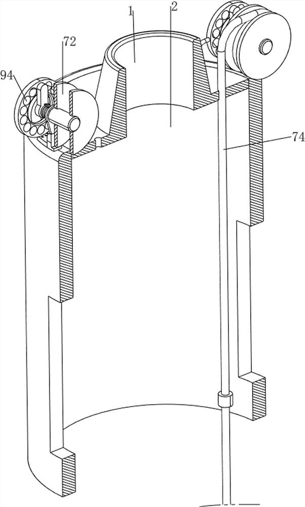
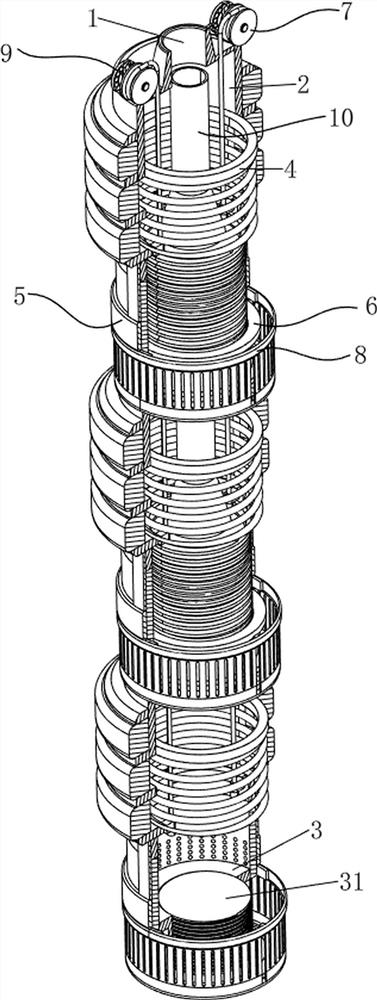
[0032] An oilfield layered oil recovery filling tool with adjustment function, such as figure 1 , image 3 and Figure 4 As shown, it includes a connecting head 1, an installation cylinder 2, an inner coil 3, an outer screw 31, a packing mechanism 4, a valve mechanism 5 and an adjusting mechanism 6. The lower side of the connecting head 1 is evenly spaced from top to bottom. There are three The installation cylinder 2, the inner side of the lower part of the installation cylinder 2 is bolted with an inner coil 3, the middle of the inner coil 3 is threaded with an outer screw 31 that is threadedly matched with it, the installation cylinder 2 is provided with a sealing mechanism 4, and the sealing mechanism 4 A valve mechanism 5 is arranged between the valve mechanism 5 and the installation cylinder 2 , and an adjustment mechanism 6 is arranged between the valve mechanism 5 and the installation cylinder 2 .
[0033] like image 3 As shown, the packing mechanism 4 includes a r...
Embodiment 2
[0039] On the basis of Example 1, as figure 1 and image 3 As shown, it also includes a filter mechanism 8. The filter mechanism 8 includes a connection block 81, a wiper plate 82, a filter cartridge 83 and a limit plate 84. The lower side of the baffle 53 is bolted symmetrically with the connection block 81. A wiping plate 82 is connected between the lower sides of the block connecting block 81 , a filter cartridge 83 is welded on the lower side of the wiping plate 82 , and a limiting plate 84 in contact with the connecting ring 51 is bolted on the lower side of the filter cartridge 83 .
[0040] During stratified oil recovery, the upward movement of the baffle 53 will drive the wiping plate 82 to move upward through the connecting block 81 to wipe the connecting ring 51, so as to prevent impurities from getting stuck on the liquid inlet hole, and the wiping plate 82 will drive the filter cartridge 83 upward. The moving cover is on the outside of the liquid inlet hole to pre...
Embodiment 3
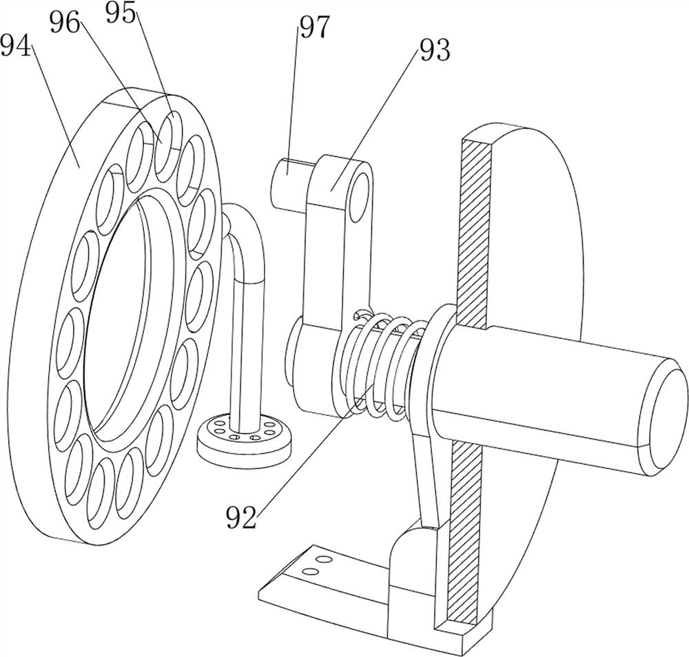
[0042] On the basis of Example 2, as figure 1 , Figure 7 and Figure 8 As shown, it also includes a safety mechanism 9. The safety mechanism 9 includes a connecting rod 91, a second return spring 92, a clamping plate 93, a chuck 94, an electromagnet 96 and an iron bump 97. The rear side of the electric winding wheel 72 A connecting rod 91 is slidably connected by a diamond-shaped shaft, a clamping plate 93 is bolted at the rear of the connecting rod 91, and an iron bump 97 is welded on the upper part of the rear side of the clamping plate 93, and the clamping plate 93 is connected with the electric reel 72. There is a second return spring 92 sleeved on the outer side of the connecting rod 91. The upper side of the connecting head 1 is symmetrically provided with a chuck 94 located directly behind the chuck 93 and used for clamping the iron bump 97. A circle of card slots 95 are evenly spaced on the front side. The card slots 95 are connected with electromagnets 96 for magne...
PUM
 Abstract
Description
Claims
Application Information
 - R&D
- Intellectual Property
- Life Sciences
- Materials
- Tech Scout
- Unparalleled Data Quality
- Higher Quality Content
- 60% Fewer Hallucinations
Browse by: Latest US Patents, China's latest patents, Technical Efficacy Thesaurus, Application Domain, Technology Topic, Popular Technical Reports.
© 2025 PatSnap. All rights reserved.Legal|Privacy policy|Modern Slavery Act Transparency Statement|Sitemap|About US| Contact US: help@patsnap.com


