Method for manufacturing a transverse segment for a puller belt of a continuously variable transmission and

A technology of continuously variable transmission and transverse section, applied in belts, applications, V-belts, etc., can solve the problems of impractical, uneconomical, insufficient stiffness and/or strength of punching, and achieve the effect of increasing the overall mechanical strength

Pending Publication Date: 2022-06-21
ROBERT BOSCH GMBH
View PDF1 Cites 0 Cited by
  • Summary
  • Abstract
  • Description
  • Claims
  • Application Information

AI Technical Summary

Problems solved by technology

Otherwise, punching becomes impractical and / or uneconomical due to insufficient rigidity and / or strength of the punching tool (ie, punching punch) used to punch out the bars

Method used


Image

  • Method for manufacturing a transverse segment for a puller belt of a continuously variable transmission and
  • Method for manufacturing a transverse segment for a puller belt of a continuously variable transmission and
  • Method for manufacturing a transverse segment for a puller belt of a continuously variable transmission and

Examples


Embodiment Construction

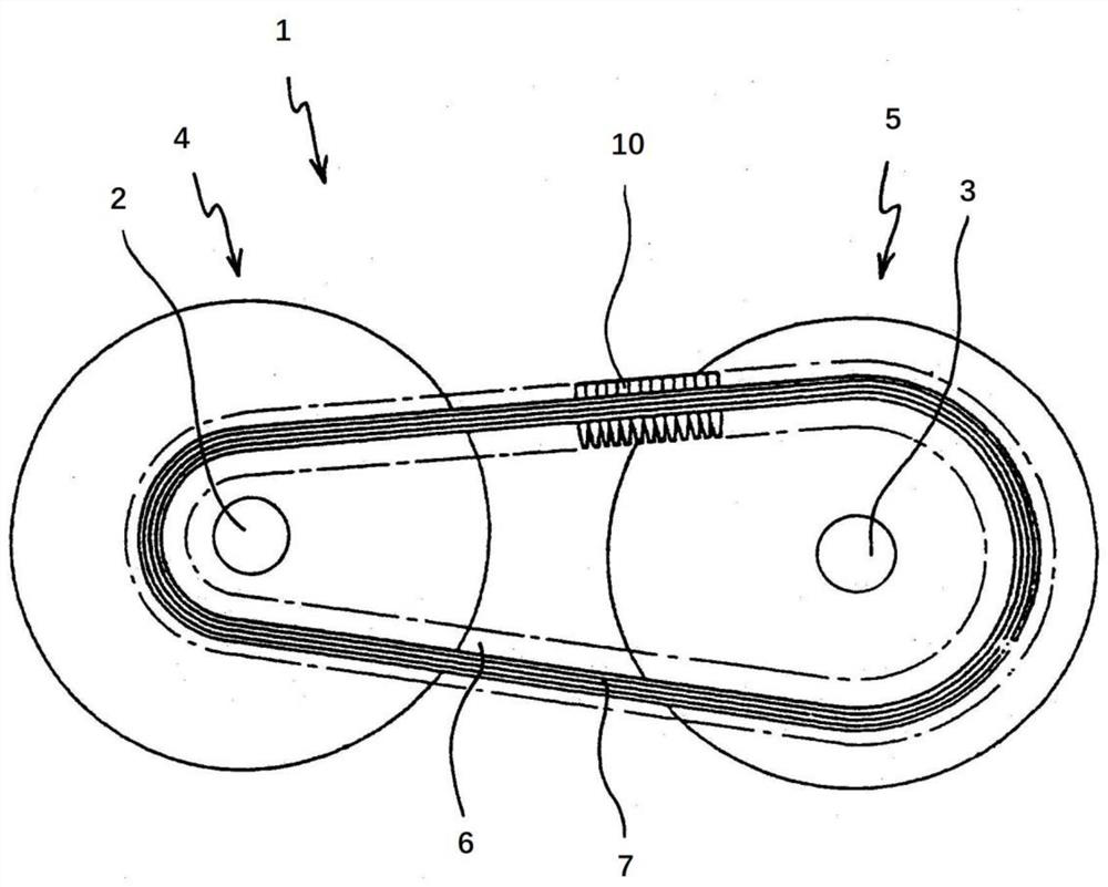
[0025] figure 1 A continuously variable transmission, for example used in a motor vehicle, is shown schematically. The continuously variable transmission is generally designated by the reference numeral 1 .

[0026] The continuously variable transmission 1 comprises two pulleys 4, 5, each of which is arranged on a corresponding pulley shaft 2, 3, respectively. The push belt 6 is arranged in a closed loop around the pulleys 4 , 5 and serves to transmit torque between the pulley shafts 2 , 3 . The pulleys 4 , 5 are each provided with two grooved pulleys, between which the respective circumferential sections of the push belt 6 are positioned and clamped so that rotation can be transmitted between the pulleys 4 , 5 .

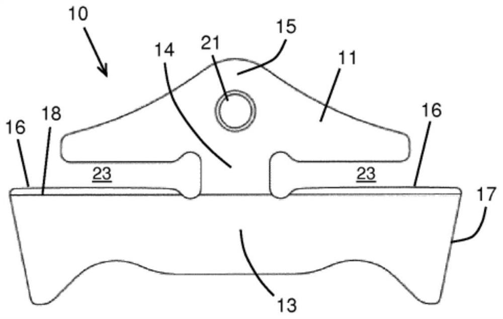
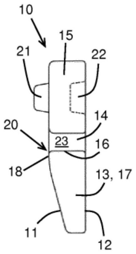
[0027] The shown push belt 6 comprises at least one loop group 7 consisting of a bundle of inter-nested continuous belts or loops. A plurality of transverse segments 10 are arranged on the ring group 7 forming a substantially continuous row along the entire circu...


PUM


Abstract

The invention relates to a method for producing a transverse section (10) for a push belt (6) from a base material (50), which transverse section defines two grooves (23) for receiving respective ring sets (7) of the push belt (6), in which method two holes (52) are punched in the base material (50) at the locations of the grooves (23) by means of two punching punches (54), the two punching punches each include a central portion (54c) and two side portions (54s) disposed on respective sides of the central portion (54c), respectively. According to the invention, at least one such side portion (54s) of the punching punch (54) is higher than a central portion (54c) of the punching punch when viewed in a cross-section of the punching punch (54). Therefore, the push belt (6) can be advantageously miniaturized by reducing the height of the hole (52) to be lower than the minimum thickness requirement of a traditional punching punch (54).

Description

technical field [0001] The present invention relates to a method for manufacturing a transverse segment as part of a push belt for a continuously variable transmission. Push belts are well known and typically comprise two sets, each set of a plurality of inter-nested continuous strips or rings, and a plurality of transverse segments in a substantially continuous row along the circumference of the sets of rings mounted on these ring sets. Such a push belt is described, for example, in European patent EP 3063432 B1, which also discloses a method for punching transverse segments from a strip of base material. Background technique [0002] In the following description of the transverse segments, the directions and dimensions mentioned are for the case where the transverse segments are part of the push belt. Thus, the longitudinal or thickness direction of the transverse segment thus corresponds to the circumferential direction of the push belt; the vertical or height direction...

Claims


Application Information

Patent Timeline
Patent Type & Authority Applications(China)
IPC IPC(8): F16G5/16B21D53/14B21D28/02
CPCF16G5/16B21D53/14B21D28/02
Inventor J·J·A·M·博格哈茨J·弗罗因德
Owner ROBERT BOSCH GMBH
Why Eureka
Try Eureka