
Fiber slicer and slicing method

A fiber slicing and slicing technology, which is applied in the direction of instruments, scientific instruments, sampling, etc., can solve the problems of unadjustable fiber length and low production efficiency, achieve high success rate, reduce installation space, and increase the number of bundles

Pending Publication Date: 2022-06-24
SHANDONG INST FOR PROD QUALITY INSPECTION
View PDF0 Cites 0 Cited by
  • Summary
  • Abstract
  • Description
  • Claims
  • Application Information

AI Technical Summary

Problems solved by technology

[0005] The purpose of the present invention is to provide a fiber slicer and a slicer method to solve the problems of low slice efficiency and unadjustable fiber length in the prior art

Method used


Image

  • Fiber slicer and slicing method
  • Fiber slicer and slicing method

Examples


Embodiment 1

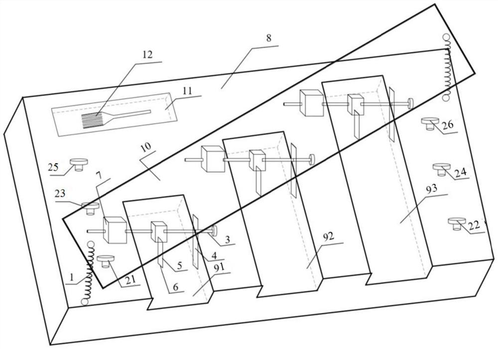
[0030] like figure 1 and figure 2 As shown, the present embodiment provides a fiber slicer, including:

[0031] The base 8 is provided with multiple groups of pulling units, and each group of pulling units is used to pull a bundle of fibers;

[0032] The mounting base 10 is erected above the base 8, and is provided with slicing units that are consistent with the number of pulling units and corresponding to them one-to-one. Each slicing unit includes two blades for transversely cutting the corresponding fibers. A ball screw 3 is arranged between the blades, and the distance between the two blades is adjusted by screwing it;

[0033] The elastic body is arranged between the base 8 and the mounting seat 10 and supports the mounting seat 10 with a downward pressing space.

[0034] The multiple sets of pulling units provided can pull multiple bundles of fibers to be cut, and a matching slicing unit is set to realize cross-cutting of different fibers to be cut by pressing, so th...

Embodiment 2

[0046] The present embodiment provides a slicing method according to the fiber slicer in Embodiment 1, comprising the following steps:

[0047] Multiple groups of pulling units are used to pull a bundle of fibers group by group, that is, the first screw 21 and the second screw 22 are used to pull a bundle, the third screw 23 and the fourth screw 24 are used to pull a bundle, and the fifth screw 25 and the first screw 25 are used to pull a bundle of fibers. The six screws 26 pull a bundle so that the three bundles of fibers are in the same horizontal plane and parallel to each other. Adjust the distance between the two blades on each slicing unit according to the required fiber length, press the mounting seat 10 and the spring 1 between the base 8 and the two blades to cross-cut the corresponding fibers. After the slicing is completed, under the rebound effect of the elastic body, The mount 10 returns to the original position. After the fiber is cross-cut, the cross-cut cut ma...


PUM


Abstract

The invention belongs to the technical field of fiber detection, and particularly relates to a fiber slicer and a slicing method.The fiber slicer comprises a base, a plurality of traction units are arranged on the base, and each traction unit is used for pulling a bundle of fibers; the mounting seat is erected above the base, slicing units which are consistent with the traction units in group number and are in one-to-one correspondence with the traction units are arranged on the mounting seat, each slicing unit comprises two blades used for transversely cutting fibers corresponding to the slicing unit, a ball screw is arranged between the blades, and the distance between the two blades is adjusted by screwing the ball screw; the elastic body is arranged between the base and the mounting seat, supports the mounting seat and is provided with a downward pressing space; according to the device, multiple bundles of different types of fibers can be transversely cut at the same time, the sheet production efficiency is improved, the sheet production time is saved, and fiber cut materials with different lengths can be obtained by adjusting the distance between the blades.

Description

technical field [0001] The invention belongs to the technical field of fiber detection, and particularly relates to a fiber slicer and a slicing method. Background technique [0002] In the process of textile inspection and testing, especially in the qualitative analysis of fiber content, the type of fiber is preliminarily judged according to the cross-section or longitudinal cross-section of the fiber. The cross-section or longitudinal section of the fiber is obtained by slicing the fiber with a fiber slicer, so the fiber slicer plays a very important role in textile testing. [0003] When using a fiber slicer to obtain a fiber longitudinal section, place the fiber into one of the grooved metal plates of the slicer, insert the other tabbed metal plate, and hold the two sides of the slicer tightly with one hand. A piece of metal plate, the tongue of the metal plate is pressed against the fibers in the groove by the gripping force, the spring device is rotated, and the fiber...

Claims


Application Information

Patent Timeline
Patent Type & Authority Applications(China)
IPC IPC(8): B26D1/04B26D7/08B26D7/26G01N1/28
CPCB26D1/04B26D7/088B26D7/2628G01N1/286G01N2001/2873B26D2007/0018
Inventor 张雪孙剑涛燕红雁王海娟刘慧慧张元孙欣
Owner SHANDONG INST FOR PROD QUALITY INSPECTION
Learn More