
Building energy-saving construction conveying device based on mechanical transmission

A technology of building energy saving and mechanical transmission, applied in the direction of conveyors, cleaning devices, conveyor objects, etc., can solve the problems of inconvenience, dust flying, etc., and achieve the effect of speeding up the drying process, spraying the area comprehensively, and saving energy

Pending Publication Date: 2022-06-24
黑龙江省建筑安装集团有限公司
View PDF0 Cites 3 Cited by
  • Summary
  • Abstract
  • Description
  • Claims
  • Application Information

AI Technical Summary

Problems solved by technology

[0004] The purpose of the present invention is to solve the following disadvantages in the prior art. Dust is attached to the outer surface of the materials in the existing building construction site, and these dusts are easily flying due to the vibration force of the conveyor belt during the transportation process. It is inconvenient to carry out water spraying and dust suppression work manually or with additional driving equipment, but a kind of building energy-saving construction conveying device based on mechanical transmission is proposed

Method used


Image

  • Building energy-saving construction conveying device based on mechanical transmission
  • Building energy-saving construction conveying device based on mechanical transmission
  • Building energy-saving construction conveying device based on mechanical transmission

Examples


Embodiment Construction

[0029] The technical solutions in the embodiments of the present invention will be clearly and completely described below with reference to the accompanying drawings in the embodiments of the present invention. Obviously, the described embodiments are only a part of the embodiments of the present invention, rather than all the embodiments.

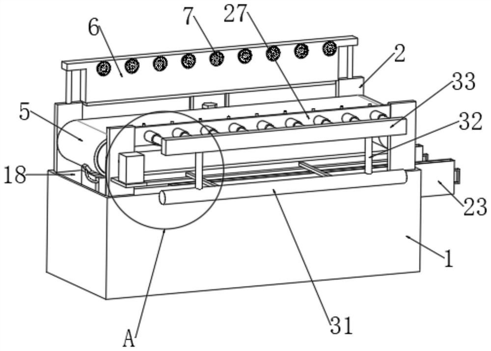
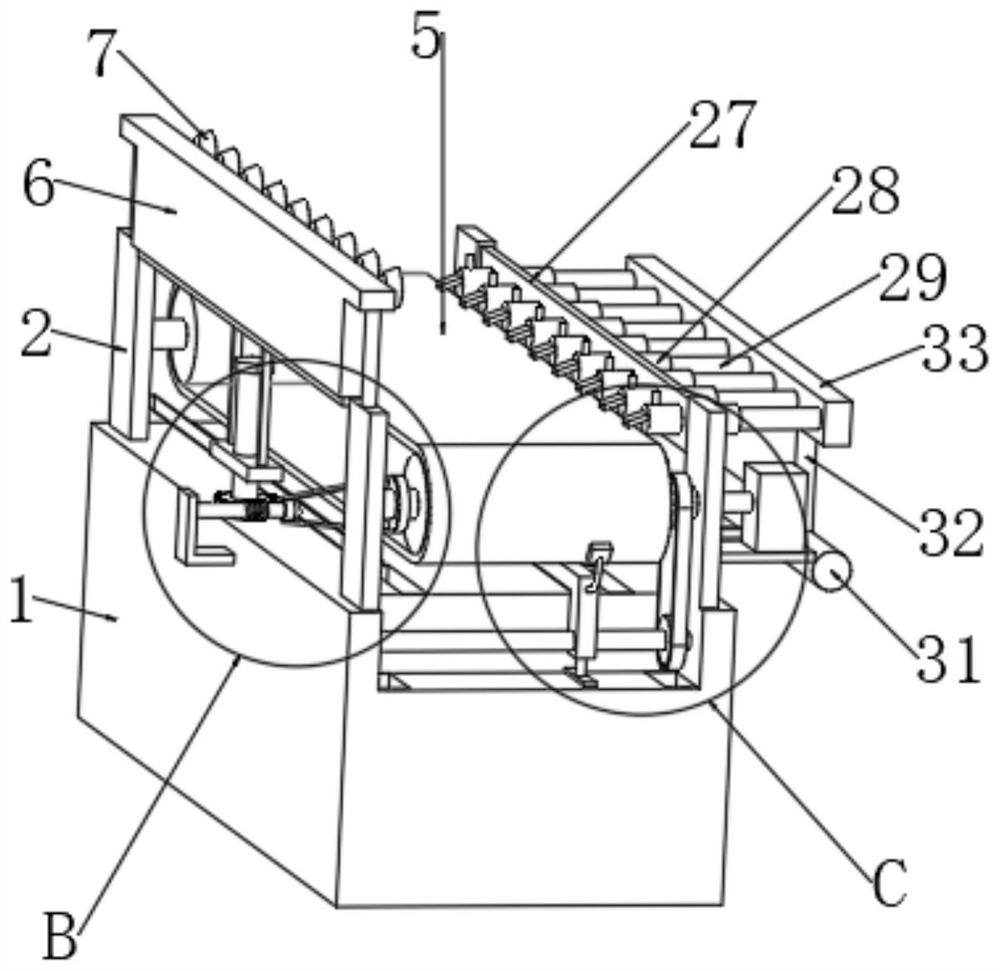
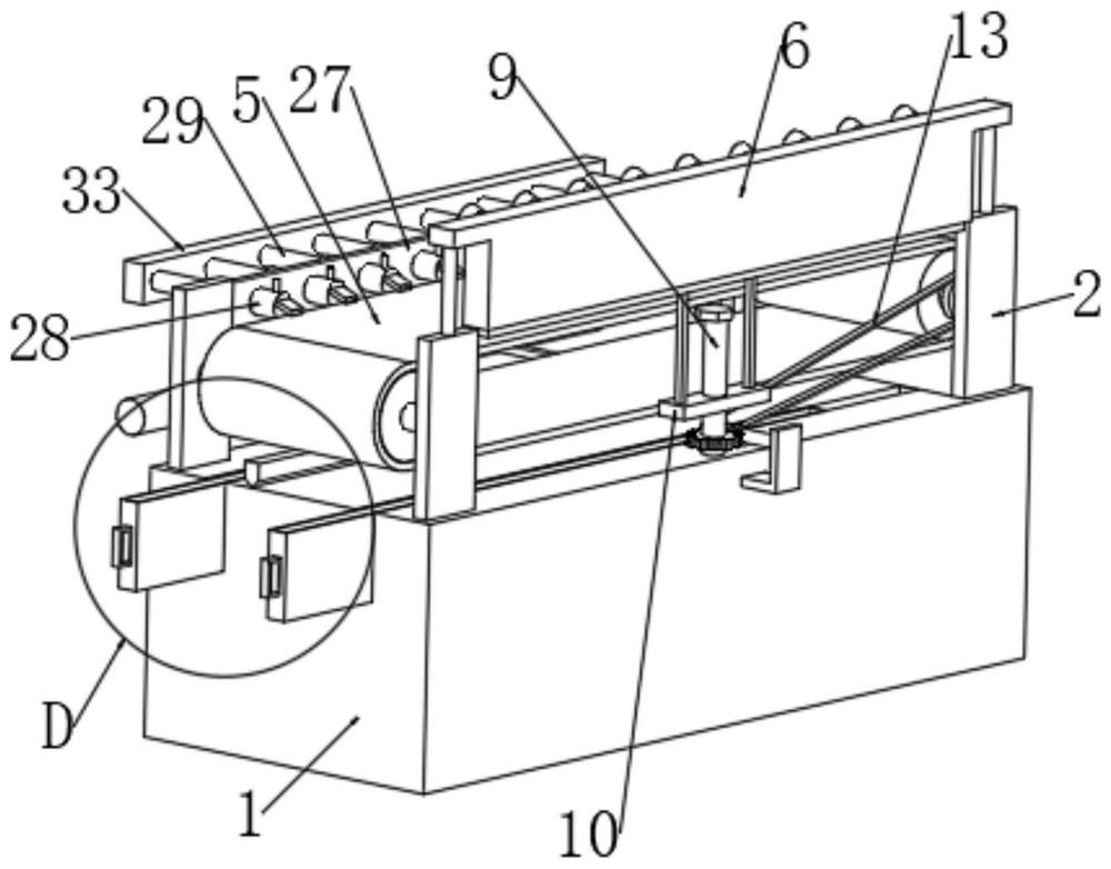
[0030] refer to Figure 1-7 , A building energy-saving construction conveying device based on mechanical transmission, comprising a platform body 1, two pairs of support plates 2 are fixedly installed on the upper surface of the platform body 1, a rotating shaft 3 is rotatably installed between the two pairs of support plates 2, and the rotating shaft 3 is fixed on the A rotating roller 4 is sleeved, and a conveyor belt 5 is wound on the two rotating rollers 4. A servo motor 21 is fixedly installed on the side wall of one of the support plates 2, and the output shaft of the servo motor 21 is fixedly connected to one end of one of the rotati...


PUM


Abstract

The invention discloses a building energy-saving construction conveying device based on mechanical transmission. The building energy-saving construction conveying device comprises a table body, two pairs of supporting plates are fixedly installed on the upper surface of the table body, rotating shafts are rotationally installed between the two pairs of supporting plates, the rotating shafts are fixedly sleeved with rotating rollers, and a conveying belt is wound around the two rotating rollers; a dust falling assembly is arranged between the two supporting plates and comprises a mounting plate fixedly mounted on the upper surfaces of the two supporting plates, a plurality of mist nozzles, a piston plate, a first reciprocating screw rod vertically and rotatably mounted on the upper surface of the table body, a first sliding block connected to the first reciprocating screw rod in a threaded and sleeving manner and a driving part; and the driving part is used for providing driving force for the first reciprocating screw rod to rotate. In the conveying process of the conveying belt, under the action of the driving component, the mist sprayers can intermittently spray water mist, so that the dust falling effect is achieved, convenience and trouble saving are achieved, an additional power system is not needed, and energy is saved.

Description

technical field [0001] The invention relates to the technical field of building construction, in particular to a conveying device for building energy-saving construction based on mechanical transmission. Background technique [0002] Construction refers to the production activities in the implementation stage of project construction. During the construction process, materials need to be conveyed by conveying devices. Usually, the materials to be conveyed are placed on the conveyor belt for conveying, and then they are conveyed to the designated position after being conveyed. Remove to use. [0003] There will be dust attached to the outer surface of the material in the existing construction site, and these dusts are easily blown up by the vibration force of the conveyor belt during the conveying process. Dust work is more inconvenient. SUMMARY OF THE INVENTION [0004] The purpose of the present invention is to solve the following shortcoming in the prior art. The outer ...

Claims


Application Information

Patent Timeline
Patent Type & Authority Applications(China)
IPC IPC(8): B65G45/14B65G45/22B65G45/24B65G15/30B01D47/06
CPCB65G45/14B65G45/22B65G45/24B65G15/30B01D47/06
Inventor 孙月领兰光尹承龙滕琨王楠野
Owner 黑龙江省建筑安装集团有限公司
Learn More