Feeding structure of solid waste treatment machine and solid waste treatment machine

A processor and feeding technology, applied in the direction of solid waste removal, conveyor objects, loading/unloading, etc., can solve problems such as clogging the feeding pipeline, and achieve the effect of maintaining smoothness, improving adaptability, and reducing clogging

Pending Publication Date: 2022-06-24
HEFEI UNIV OF TECH
View PDF0 Cites 0 Cited by
  • Summary
  • Abstract
  • Description
  • Claims
  • Application Information

AI Technical Summary

Problems solved by technology

[0004] Aiming at the deficiencies of the prior art, the invention discloses a solid waste treatment machine feeding structure and a solid waste treatment machine, which can solve the problem of solid waste clogging the feeding pipeline during the transmission process

Method used


Image

  • Feeding structure of solid waste treatment machine and solid waste treatment machine
  • Feeding structure of solid waste treatment machine and solid waste treatment machine
  • Feeding structure of solid waste treatment machine and solid waste treatment machine

Examples


Embodiment 1

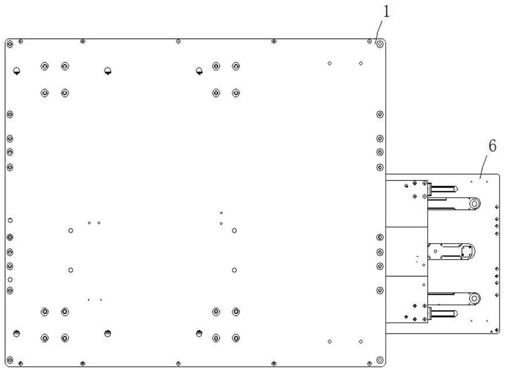
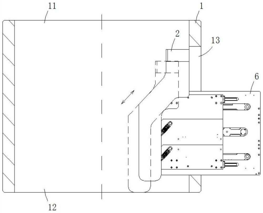
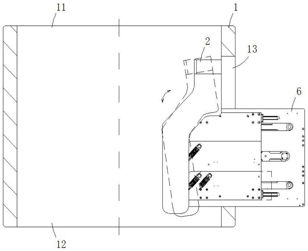
[0028] like Figure 1 to Figure 6 As shown, the feeding structure of the solid waste treatment machine according to the embodiment of the present invention includes a feeding channel 1, a baffle 2, an elastic member 3, a slider, a driving cylinder, and a base 6, which can be on one side of the feeding channel 1. A through hole 13 is formed by means including but not limited to turning, the base 6 can be fixedly installed in the through hole 13 by means including but not limited to bolt connection, the baffle 2 is installed inside the feed channel 1, and the feed channel 1 It includes a feed port 11 and a discharge port 12 , the feed port 11 is connected to the discharge port 12 , the feed port 11 is located at the top of the feed channel 1 , and the discharge port 12 is located at the bottom end of the feed channel 1 . It is easy to understand that the solid waste enters from the feed port 11 and falls from the discharge port 12 under the action of gravity.

[0029] The slide...

Embodiment 2

[0036] like Figure 1 to Figure 6 As shown, in the feeding structure of the solid waste treatment machine according to the embodiment of the present invention, in order to solve the problem of how to maintain the support baffle 2 in the whole process more stably, the slider includes a support slider 4, and the support slider 4 is located on the top of the base 6 For installation, the support slider 4 is connected to the top of the baffle plate 2 , and the support slider 4 is connected to a driving oil cylinder 41 . It is easy to understand that a chute 61 can be formed on the base 6 to guide the support slider 4 by means including but not limited to turning. Correspondingly, the telescopic direction of the driving cylinder 41 and the extension direction of the chute 61 are the same.

[0037] In order to solve the problem of how to adjust the posture of the baffle 2 more flexibly, the slider includes an auxiliary slider 5, which is installed at the bottom of the base 6, the auxil...


PUM


Abstract

The invention discloses a feeding structure of a solid waste treatment machine and the solid waste treatment machine. Comprising a feeding channel, a baffle, an elastic piece, a sliding block, a driving oil cylinder and a base, the base is installed on one side of the feeding channel, the sliding block is slidably connected with the base, the driving oil cylinder is connected with the base and the sliding block, the elastic piece is connected with the sliding block and the baffle, the baffle comprises a first plane and a second plane, and the extending direction of the first plane is parallel to the axis direction of the feeding channel; the extending direction of the second plane is obliquely installed relative to the axis direction of the feeding channel, the extending direction of the elastic piece is parallel to the extending direction of the second plane, and the extending direction of the driving oil cylinder is perpendicular to the axis direction of the feeding channel. The problem that solid waste blocks a feeding pipeline in the conveying process can be solved.

Description

technical field [0001] The invention relates to the technical field of industrial solid waste treatment, in particular to a feed structure of a solid waste treatment machine and a solid waste treatment machine. Background technique [0002] Solid waste can be roughly divided into three types: domestic waste, general industrial solid waste and hazardous waste. In addition, solid waste includes agricultural solid waste, construction waste and spoil. If solid waste is not properly treated or utilized, it will pollute the atmosphere, water and soil, and endanger human health. Solid waste also has the characteristics of wide sources, various types, large quantities and complex components. Therefore, the focus of the treatment work is to collect, transport and store waste according to the different characteristics of waste, and then make reasonable use and treatment to reduce environmental pollution and turn waste into treasure as much as possible. [0003] In the prior art, it ...

Claims


Application Information

Patent Timeline
Patent Type & Authority Applications(China)
IPC IPC(8): B65G47/74B65G69/00B09B3/35
CPCB65G47/74B65G69/00B09B3/00
Inventor 周春财高飞月孙金科陈旭蒲天
Owner HEFEI UNIV OF TECH
Why Eureka
Try Eureka