
Gear ring power output device of rotary opposed piston engine

A technology of opposed piston and power output, applied in the direction of transmission, engine components, gear transmission, etc., can solve the problems of complex structure of the power output device, weaken the advantages of the simple structure of the rotary opposed piston engine, etc., and achieve a simple and stable structure. , to meet the effect of the compression ratio

Pending Publication Date: 2022-06-24
BEIJING INSTITUTE OF TECHNOLOGYGY
View PDF0 Cites 0 Cited by
  • Summary
  • Abstract
  • Description
  • Claims
  • Application Information

AI Technical Summary

Problems solved by technology

[0003] In a rotary opposed piston engine, every two opposed pistons are connected to a piston connecting shaft, and the two piston connecting shafts are opposite to each other and supported by the engine block; in order to realize the four strokes of exhaust, intake, compression and expansion, The two sets of pistons need to drive the two piston connecting shafts to rotate in the same direction in different modes; while the existing power output device has a complicated structure, which seriously weakens the advantages of the simple structure of the rotary opposed piston engine

Method used


Image

  • Gear ring power output device of rotary opposed piston engine
  • Gear ring power output device of rotary opposed piston engine
  • Gear ring power output device of rotary opposed piston engine

Examples


Embodiment Construction

[0056] The technical solutions in the embodiments of the present invention will be clearly and completely described below with reference to the accompanying drawings in the embodiments of the present invention. Obviously, the described embodiments are only a part of the embodiments of the present invention, but not all of the embodiments. Based on the embodiments of the present invention, all other embodiments obtained by those of ordinary skill in the art without creative efforts shall fall within the protection scope of the present invention.

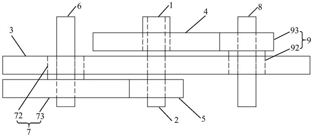
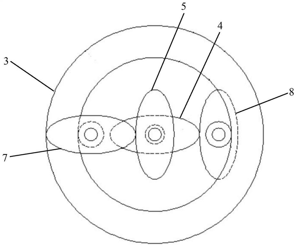
[0057] see attached figure 1 to the attached Figure 11 , the embodiment of the present invention discloses a power output device of a rotary opposed piston engine ring gear, comprising:

[0058] the first piston connecting shaft 1; the first piston connecting shaft 1 is provided with a first shaft hole 11;

[0059] The second piston connecting shaft 2; one end of the second piston connecting shaft 2 is coaxially nested inside the f...


PUM


Abstract

The invention discloses a gear ring power output device of a rotary opposed piston engine. The gear ring power output device comprises a first piston connecting shaft, a second piston connecting shaft, a first gear assembly, a second gear assembly and a gear ring. A first shaft hole is formed in the first piston connecting shaft; one end of the second piston connecting shaft is coaxially nested in the first shaft hole, and the other end of the second piston connecting shaft coaxially penetrates through the first gear assembly; the second gear assemblies are located on the two sides of the second piston connecting shaft and engaged with the first gear assembly. Meanwhile, the gear ring is meshed with the second gear assembly; the structure is simple, the first piston connecting shaft and the second piston connecting shaft are driven by the pistons to rotate, the first gear assembly and the second gear assembly as well as the second gear assembly and the gear ring are always kept meshed, power is integrated to the second piston connecting shaft, and power output of the rotary opposed piston engine is achieved; therefore, different rotation modes of the engine piston are achieved, and the specific compression ratio of the engine is met.

Description

technical field [0001] The invention relates to the technical field of internal combustion engines, and more particularly to a power output device for a rotary opposed piston engine ring gear. Background technique [0002] Benefiting from the special structure of the rotary opposed piston engine, at the same speed, the power frequency of the rotary opposed piston engine is twice that of the traditional four-stroke internal combustion engine, and the air exchange process is more complete than that of the two-stroke engine, so under the same speed conditions , The theoretical power density of the rotary opposed piston engine is about twice that of the traditional four-stroke internal combustion engine, which can effectively realize the miniaturization and light weight of the internal combustion engine. In addition, the rotary opposed piston engine has no crank connecting rod mechanism, simple structure, stable operation and low noise. Different from the traditional four-stroke...

Claims


Application Information

Patent Timeline
IPC IPC(8): F02B75/24F02B77/00F16H1/20
CPCF02B75/24F02B77/00F16H1/20Y02T10/12
Inventor 高建兵王余枫王雨阳雷志成刘天浩柳景灿王鑫杰马朝臣
Owner BEIJING INSTITUTE OF TECHNOLOGYGY
Learn More