
GTF engine gearbox with adjustable supporting rigidity

A technology for supporting rigidity and engine, applied in the direction of gear transmission, gear lubrication/cooling, belt/chain/gear, etc., which can solve the problem of low assembly precision, high difficulty and uneven force of splines in segmented herringbone ring gear and other problems, to achieve uniform load distribution, increase elasticity, and solve the effect of uneven force on splines

Pending Publication Date: 2022-06-24
NORTHWESTERN POLYTECHNICAL UNIV
View PDF2 Cites 0 Cited by
  • Summary
  • Abstract
  • Description
  • Claims
  • Application Information

AI Technical Summary

Problems solved by technology

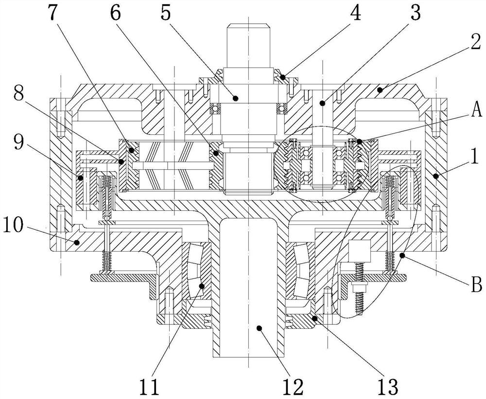
[0007] In order to avoid the deficiencies of the prior art, the present invention proposes a GTF engine gearbox with adjustable support stiffness, which adopts segmented planetary gears, which avoids the problem of low assembly accuracy and difficulty of the segmented herringbone ring gear. It also solves the phenomenon of uneven stress on the splines caused by manufacturing and installation errors of the segmented sun gear; the stiffness adjustment device can adjust the support stiffness of the herringbone inner ring gear to ensure that the inner ring gear always maintains Optimal support rigidity keeps the vibration and noise of the gearbox at the lowest state, and the transmission is more stable; the elastic shaft with symmetrical grooves can realize the elastic support of the planetary gear, which is beneficial to the load sharing of the GTF gearbox

Method used


Image

  • GTF engine gearbox with adjustable supporting rigidity
  • GTF engine gearbox with adjustable supporting rigidity
  • GTF engine gearbox with adjustable supporting rigidity

Examples


Embodiment

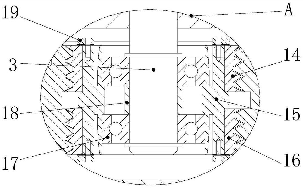
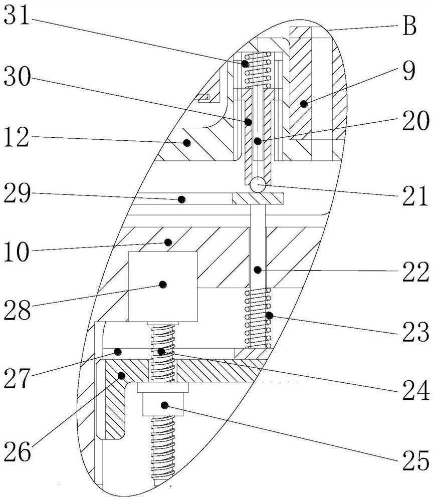
[0043] refer to Figure 1-8 , the present invention is a GTF engine gearbox with adjustable support stiffness, including a box body 1, the box body 1 and the upper box cover 2 are generally fixed by screws, the input shaft 5 penetrates the upper box cover 2, and is connected with the upper box cover 2. They are rotatably connected by deep groove ball bearings. The outer surface of the port of the upper box cover 2 is fixedly connected with the input shaft end cover 4 by screws. The input shaft end cover 4 is sleeved on the input shaft 5 to position the input shaft 5. The inner end surface of 2 is provided with a plurality of star wheel shafts 3 evenly running through the circumferential direction. The star wheel shaft 3 is fixedly connected with the upper case cover 2 by screws. The lower end of each star wheel shaft 3 is provided with a first star wheel 14 and a second star wheel 14. The star wheel 16 , the first star wheel 14 , the second star wheel 16 and the star wheel sha...


PUM


Abstract

The invention discloses a GTF engine gearbox with adjustable supporting rigidity, and belongs to the technical field of aircraft power. Comprising a box body, an input shaft and an output shaft, the input shaft and the output shaft respectively penetrate through the upper box cover and the lower box cover and are driven in the box body through a gear mechanism; the gear mechanism comprises a sun gear, a star wheel combination device, an inner gear ring and an inner gear ring installation disc, the sun gear is coaxially installed at the inner end of the input shaft, and the inner gear ring is coaxially installed on the end face of the inner end of the output shaft through the inner gear ring installation disc 8 and is coaxial with the sun gear 6; the multiple star wheel combination devices are arranged between the sun wheel and the inner gear ring in the circumferential direction and engaged with the sun wheel and the inner gear ring. And a rigidity adjusting device is arranged on the lower box cover. According to the invention, the sectional type planet gear is adopted, so that the phenomenon of non-uniform stress of a spline caused by manufacturing and mounting errors of a sectional sun gear is solved; the rigidity adjusting device can adjust the supporting rigidity of the herringbone inner gear ring, and it is guaranteed that the inner gear ring keeps the optimal supporting rigidity all the time at different rotating speeds.

Description

technical field [0001] The invention belongs to the technical field of aircraft power, and in particular relates to a GTF engine gearbox with adjustable support stiffness. Background technique [0002] Reducing fuel consumption, reducing emissions and reducing vibration and noise are the main development directions of the next generation of aero-engines. [0003] At present, in high-thrust and high-bypass ratio turbofan engines, the fan is mostly directly driven by the low-pressure turbine. This design has an inherent disadvantage, that is, neither the supercharger compressor nor the low-pressure turbine work at their optimum speed. Compared with the traditional twin-rotor turbofan engine, the gear-driven fan (GTF) engine has no fundamental changes to the core engine, but only adds a gear box to make the engine's fan work independently of the low-pressure compressor and turbine, thereby improving fuel combustion efficiency. Higher, lower fan speed, with the advantages of lo...

Claims


Application Information

Patent Timeline
Patent Type & Authority Applications(China)
IPC IPC(8): F16H1/28F16H1/32F16H1/34F16H57/021F16H57/022F16H57/023F16H57/028F16H57/031F16H57/04F16H57/08
CPCF16H1/2809F16H1/2818F16H1/34F16H57/028F16H57/021F16H57/031F16H57/023F16H57/08F16H57/0464F16H57/0486F16H2001/327F16H2057/0221
Inventor 王三民邹浩然刘琳琳李志宾李林林彭麒安李飞
Owner NORTHWESTERN POLYTECHNICAL UNIV
Learn More