Movable target capable of rotating variously
A moving target and movable technology, applied in the field of moving targets, can solve the problems of no moving function and inconvenience for training personnel, and achieve the effect of increasing the difficulty of shooting, improving the shooting technology, and being convenient for handling.
- Summary
- Abstract
- Description
- Claims
- Application Information
AI Technical Summary
Problems solved by technology
Method used
Image
Examples
Embodiment 1
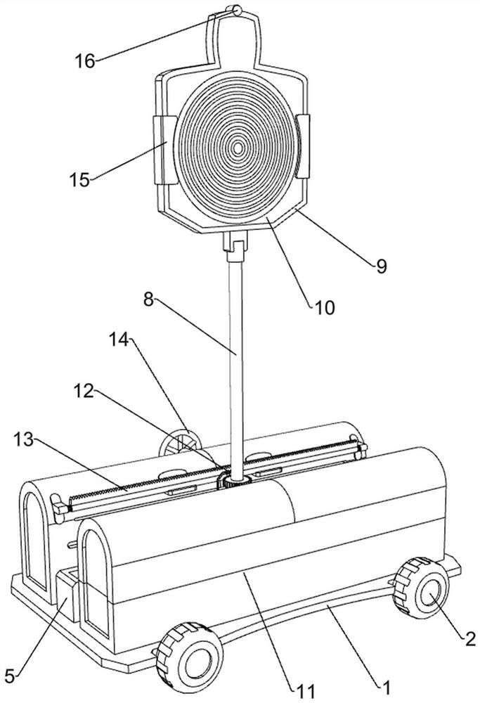
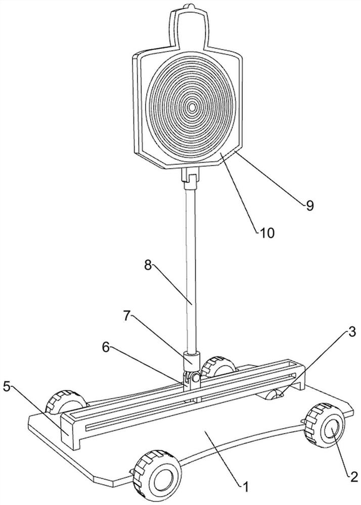
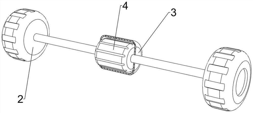
[0035] A movable and variously rotating moving target, refer to figure 1 , figure 2 , image 3 , Figure 4 , Figure 5 , Image 6 , Figure 7 , Figure 8 , Figure 9 , Figure 11 and Figure 12, including the bottom plate 1, the wheel 2, the protective shell 3, the biaxial motor 4, the electric slide rail 5, the electric slider 6, the rotating block 7, the rotating rod 8, the rotating plate 9, the target plate 10, the swing mechanism 11, the card position The mechanism 12 and the rotating mechanism 13, a protective shell 3 is welded in the middle of the inner right side of the bottom plate 1, a biaxial motor 4 is installed inside the protective shell 3, and the output shafts on both sides of the biaxial motor 4 are connected with wheels 2 for driving the device to move. 2 is connected with the bottom plate 1 in a rotary manner, the inner left side of the bottom plate 1 is also rotatably connected with a wheel 2, an electric sliding rail 5 is installed in the horizont...
Embodiment 2
[0038] On the basis of Example 1, refer to figure 1 , Figure 4 , Figure 5 , Image 6 , Figure 8 and Figure 9 , including the rocking mechanism 11 including the support frame 110, the guide plate 111, the U-shaped plate 112, the turntable 113, the connecting plate 114, the clamping plate 115 and the first return spring 116, the top of the bottom plate 1 is welded on the front and rear sides of the support frame 110 , the outer wall of the support frame 110 is coated with anti-rust paint, which is not easy to rust and age. The middle part of the support frame 110 is connected with a guide plate 111, and the middle part of the guide plate 111 is provided with a guide groove. A U-shaped plate 112 is connected to the front side, a slider is slidably connected to the front side of the U-shaped plate 112, a turntable 113 is connected to the front side of the slider, and a turntable 113 is also connected to the rear side of the rotating block 7. Each support frame 110 is slid...
Embodiment 3
[0041] On the basis of Example 2, refer to figure 1 , Figure 7 and Figure 8 , the clamping mechanism 12 includes a first guide rod 120, a V-shaped rod 121, a second return spring 122, a mounting block 123, a first extrusion rod 124, a first return spring 125 and a second extrusion rod 126, the rotating block 7. A first guide rod 120 is connected in the middle of the rear, and a V-shaped rod 121 is slidably connected to the outer front side of the first guide rod 120. The V-shaped rod 121 is used to fix the rotating block 7 and the rotating rod 8. The rotating rod 8 There are card slots evenly arranged on the outer side of the lower part of the V-shaped rod 121. The V-shaped rod 121 cooperates with the card grooves on the rotating block 7 and the rotating rod 8. A second return spring 122 is connected between the V-shaped rod 121 and the first guide rod 120, and the second The return spring 122 is sleeved on the first guide rod 120, and a mounting block 123 is welded on the...
PUM
 Abstract
Description
Claims
Application Information
 - R&D
- Intellectual Property
- Life Sciences
- Materials
- Tech Scout
- Unparalleled Data Quality
- Higher Quality Content
- 60% Fewer Hallucinations
Browse by: Latest US Patents, China's latest patents, Technical Efficacy Thesaurus, Application Domain, Technology Topic, Popular Technical Reports.
© 2025 PatSnap. All rights reserved.Legal|Privacy policy|Modern Slavery Act Transparency Statement|Sitemap|About US| Contact US: help@patsnap.com


