Friction stir welding tool fracture failure detection device and method

A technology of friction stir welding and stirring tools, which is applied in the direction of measuring devices, manufacturing tools, welding equipment, etc., can solve the problems of scrapped processed products, prone to fracture and failure, and the production rhythm cannot meet the processing rhythm requirements of large batches of products, etc., to achieve accurate The effect of improving the rate and reducing the possibility of detection errors

Pending Publication Date: 2022-06-24
青云工业(辽宁)有限公司
View PDF11 Cites 1 Cited by
  • Summary
  • Abstract
  • Description
  • Claims
  • Application Information

AI Technical Summary

Problems solved by technology

[0004] Due to the split structure design of the stationary shoulder and the stirring tool during the friction stir welding process of the stationary shoulder, the stirring tool is generally in the form of a slender cylinder, and the stirring tool bears a large upsetting force and lateral force during the entire welding process. and forward resistance, it is easier to cause fracture failure; and due to the flat pushing effect of the static shoulder in the entire processing process, it is difficult to find the fracture of the stirring tool from the upper surface of the weld. In automatic production, only by manually observing the stirring tool after welding to know if the stirring tool is broken
[0005] In the automatic continuous production process, it is impossible to manually observe whether the mixing tool is broken after each part is produced, and then start the production of the next part. Observation and judgment also increase the workload and work intensity of the operator. At the same time, if the stirring tool is not found in time after the friction stir welding of the static shoulder, and the product processing continues, all subsequent processed products will be scrapped. cause large economic losses

Method used


Image

  • Friction stir welding tool fracture failure detection device and method
  • Friction stir welding tool fracture failure detection device and method
  • Friction stir welding tool fracture failure detection device and method

Examples


Embodiment Construction

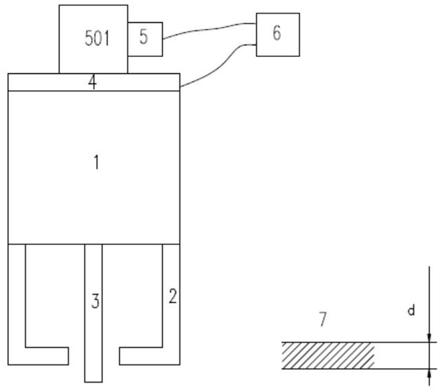
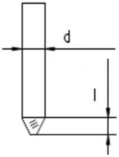
[0027] The detection device for the fracture and failure of the friction stir welding tool of the present invention includes a handpiece 1, a main shaft connected to a motor 501 is arranged in the handpiece 1, a fixed stationary shoulder 2 is arranged on the handpiece 1, and a stirring shaft is arranged on the main shaft. The tool 3, the stirring tool 3 is protruded from the through hole on the stationary shaft shoulder 2, and is characterized in that: a pressure sensor 4 and a torque sensor 5 are arranged between the main shaft and the motor 501, the pressure sensor 4 and the torque sensor 5 and a detection module 6 connected.

[0028] The handpiece 1 can be in the form of an electric spindle in which the drive of the motor 501 and the drive of the main shaft are integrated together, or the form of a mechanical spindle in which the drive of the motor 501 and the drive of the main shaft are separated.

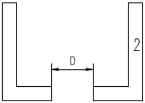
[0029] The stationary shaft shoulder 2 is bowl-shaped and has a through ho...


PUM

PropertyMeasurementUnit
thicknessaaaaaaaaaa

Abstract

The invention relates to an online detection device for fracture failure of a friction stir welding tool and a detection method using the device. According to the device capable of judging whether the stirring tool is broken or not in the friction stir welding process of the stationary shaft shoulder in real time and the detection method using the device, on one hand, the workload of operators is reduced, on the other hand, reminding can be conducted in time when the needle is broken, and unnecessary economic losses are avoided. The friction stir welding tool fracture failure detection device comprises a machine head, a main shaft connected with a motor is arranged in the machine head, a fixed static shaft shoulder is arranged on the machine head, a stirring tool is arranged on the main shaft, and the stirring tool extends out of a through hole in the static shaft shoulder. The device is characterized in that a pressure sensor and a torque sensor are arranged between the main shaft and the motor, and the pressure sensor and the torque sensor are connected with a detection module.

Description

technical field [0001] The invention relates to an on-line detection device for fracture failure of a friction stir welding welding tool and a detection method using the device. More specifically, it is an on-line detection device that can realize the fracture failure of stirring tools during static shoulder friction stir welding and a real-time detection method using the device. Background technique [0002] The static shoulder friction stir welding is developed on the basis of the traditional friction stir welding. During the welding process, the static shoulder only slides on the surface of the welded sample, and does not rotate with the stirring tool at a high speed. The upper surface of the static shoulder friction stir welding seam is excellent in shape, without the characteristics of conventional friction stir welding seams such as flash and arc, and the symmetry of the structure and properties of the advancing side and the retreating side is good, and the post-weld p...

Claims


Application Information

Patent Timeline
Patent Type & Authority Applications(China)
IPC IPC(8): G01L5/00G01L3/00B23K20/26B23K20/12
CPCG01L5/00G01L3/00B23K20/26B23K20/122
Inventor 纪宇李红英赵兰芬
Owner 青云工业(辽宁)有限公司
Why Eureka
Try Eureka