
Coaxial connector

A coaxial connector, contact arm technology, applied in the direction of connection, two-part connection device, contact parts, etc., can solve the problems of insufficient elastic restoring force of the contact arm, small support effect of the contact arm, and inability to make ultra-thin requirements. The effect of increasing elastic deformation and reducing thickness

Pending Publication Date: 2022-06-24
LINKCONN ELECTRONICS
View PDF1 Cites 0 Cited by
  • Summary
  • Abstract
  • Description
  • Claims
  • Application Information

AI Technical Summary

Problems solved by technology

[0003] The coaxial connector is usually plugged with a plug, and the plug is connected with a cable. Therefore, the total thickness of the coaxial connector and the cable can be reduced to meet the ultra-thin requirements of electronic equipment, but the cable is a must. Indispensable components, unable to meet ultra-thin requirements, usually the coaxial connector should be kept to the minimum to meet market demand
[0004] Please refer to China Utility Model Patent Announcement No. 203800210, which includes an insulating body and a movable terminal and a fixed terminal clamped in the insulating body. In order to increase the elastic deformation of the movable terminal, the movable terminal is provided with a pair of supporting springs and supported On the insulating body, the supporting shrapnel is connected to the contact arm in the middle of the moving terminal through both ends, but the supporting effect on the contact arm of the moving terminal is small, and sometimes there is a problem of insufficient elastic recovery force after the contact arm is squeezed. In miniaturized coaxial connectors, the yield strength or elastic recovery force of the terminal is a very important research that can

Method used


Image

  • Coaxial connector
  • Coaxial connector
  • Coaxial connector

Examples


Embodiment Construction

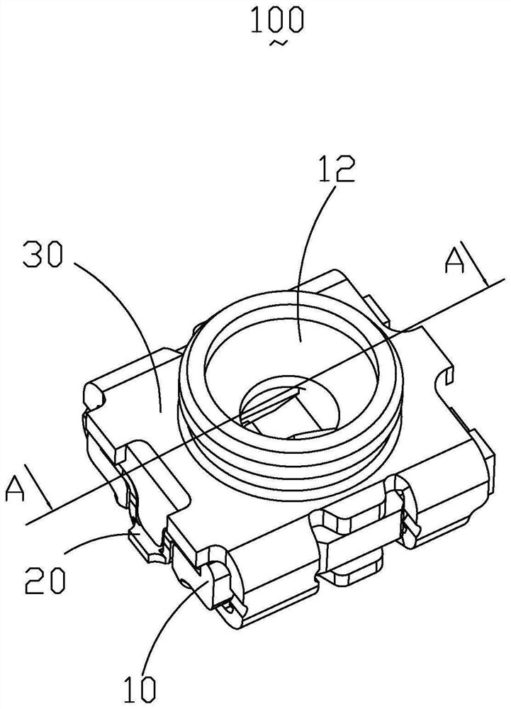
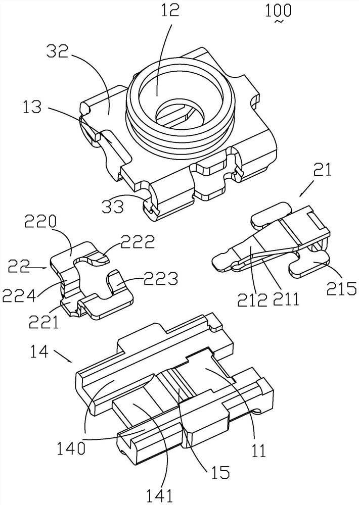
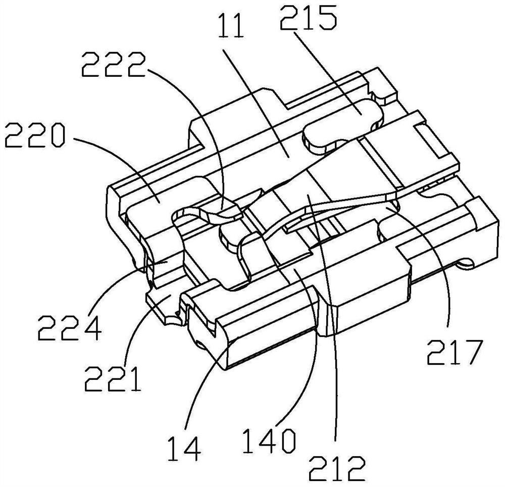
[0023] see Figure 1 to Figure 3 As shown, a preferred embodiment of the present invention discloses a coaxial connector 100, which includes an insulating body 10, a terminal 20 mounted on the insulating body 10, and a housing 30 held outside the insulating body 10, the terminal 20 It has a movable terminal 21 and a fixed terminal 22 that are in contact with each other. In this embodiment, the movable terminal 21 elastically contacts the lower side of the fixed terminal 22, and when the plug is inserted (not shown), it pushes the movable terminal 21 moves, so that the movable terminal 21 and the fixed terminal 22 are disconnected from each other. At this time, the plug and the movable terminal 21 are electrically connected. Therefore, the movable terminal 21 is relative to the fixed terminal 22, that is, the moving deformation of the movable terminal 21. The space is large; in the initial position, the movable terminal 21 elastically abuts on the fixed terminal 22, and when th...


PUM


Abstract

The invention discloses a coaxial connector, which comprises an insulating body, a terminal arranged on the insulating body and a shell fixedly held outside the insulating body, the insulating body is provided with an accommodating cavity for accommodating the terminal and a through hole penetrating upwards, the terminal is provided with a movable terminal and a fixed terminal which are in contact with each other, and the movable terminal and the fixed terminal are in contact with each other. The movable terminal and the fixed terminal are respectively inserted into the accommodating cavity of the insulating body, and the fixed terminal is provided with a fixed part fixedly held on the insulating body, a welding pin connected with the fixed part and a contact part; the movable terminal is provided with an installation part fixedly held on the insulation body, a supporting arm connected with the installation part and a contact arm, the contact arm is located on the upper side of the supporting arm and abuts against the contact part, and the installation part is provided with a welding part.

Description

technical field [0001] The invention relates to a coaxial connector, in particular to a coaxial connector used in the communication field. Background technique [0002] Smartphones, Pads and laptops have become indispensable electronic devices in people's lives. These devices need to have communication functions to realize data transmission, such as network connection, etc. However, the current electronic devices are very thin, and the internal connection parts also need It is very small, such as a coaxial connector installed in an electronic device. The coaxial connector is a radio frequency component that plays a role in communication. [0003] The coaxial connector is usually plugged into a plug, and the plug will be connected with a cable. Therefore, the total thickness of the coaxial connector and the cable can be reduced to meet the ultra-thin requirements of the electronic device, but the cable must be Indispensable components, cannot meet ultra-thin requirements, us...

Claims


Application Information

Patent Timeline
IPC IPC(8): H01R24/38H01R24/50H01R13/02
CPCH01R24/38H01R24/50H01R13/02
Inventor 朱昭晖王佳文
Owner LINKCONN ELECTRONICS
Learn More