Shoes

A technology for shoes and shoe uppers, applied in the fields of footwear, medical science, clothing, etc., can solve problems such as development that has not yet been promoted

Pending Publication Date: 2022-06-28
ASICS CORP
View PDF1 Cites 0 Cited by
  • Summary
  • Abstract
  • Description
  • Claims
  • Application Information

AI Technical Summary

Problems solved by technology

However, no technology has been developed to reduce the burden on the posterior tibial tendon in order to prevent posterior medial tibial stress syndrome

Method used


Image

  • Shoes
  • Shoes
  • Shoes

Examples


Embodiment approach 1

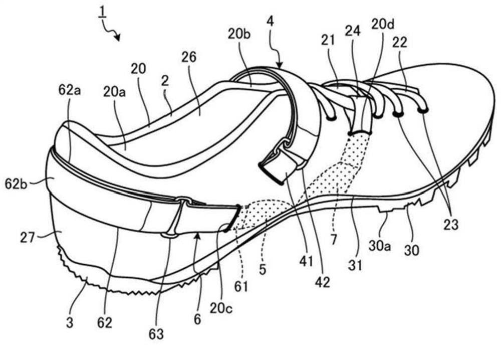
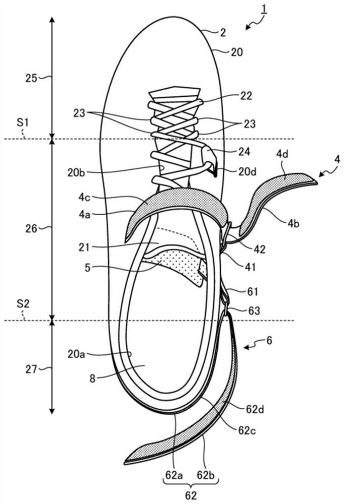
[0078] figure 2 It is a perspective view of the shoe 1 according to Embodiment 1 of the present invention. image 3 It is a plan view of the shoe 1 of the first embodiment. Figure 4 It is a foot inner side view of the shoe 1 of the first embodiment. Figure 2 to Figure 4 In the figure, only the shoe 1 for the left foot is shown. Since the shoes 1 for the left foot and the right foot have a left-right symmetrical structure, only the shoe 1 for the left foot will be described in this embodiment, and the description of the shoe 1 for the right foot will be omitted. In the present embodiment, the shoes 1 are spiked shoes for track and field, but may be running shoes or shoes for sports such as soccer, basketball, and volleyball. The shoe 1 includes an upper 2 , a sole 3 , an adjuster belt 4 , a first supporting material 5 , a first pulling material 6 and a second supporting material 7 .

[0079] The shoe upper 2 includes a shoe upper body 20 , a shoe tongue 21 and a shoelace...

Embodiment approach 2

[0108] Figure 12 It is a perspective view of 1A of shoes of Embodiment 2 of this invention. In the shoe 1A of the second embodiment, the structure of the first pulling material 6A is different from that of the shoe 1 of the first embodiment. In addition, in Embodiment 2, the same code|symbol is attached|subjected to the part which overlaps with the said Embodiment 1, and description is abbreviate|omitted.

[0109] The first lifting material 6A passes through the medial portion of the foot from the inside to the outside of the upper 2 in the midfoot portion 26 of the upper, and extends along the rear foot portion 27 of the upper, and can be fixed to the rear foot portion 27 of the upper. The first pulling material 6A has one belt 64a and a belt fixing portion 64b. Regarding the material of the belt 64a and the belt fixing portion 64b, for example, knitted fabric, braided fabric, synthetic leather, or resin can be used.

[0110] The strap 64a is attached to the medial portio...

Embodiment approach 3

[0113] Figure 13 It is a perspective view of shoe 1B according to Embodiment 3 of the present invention. Figure 14 It is a plan view of the shoe 1B of the third embodiment. Figure 15 It is a foot inner side view of the shoe 1B of the third embodiment. In the shoe 1B of the third embodiment, the structure of the first pulling material 6B is different from that of the shoe 1 of the first embodiment. In addition, in Embodiment 3, the same code|symbol is attached|subjected to the part which overlaps with the said Embodiment 1, and description is abbreviate|omitted.

[0114] like Figure 13 As shown, the 1st pulling material 6B has the 1st belt 65a, the 2nd belt 65b, the fixing belt 65c, the connection part 65d, and the connection part 65e. The fixing strap 65c and the connecting portion 65d are located in the inner side portion of the midfoot portion 26 of the shoe upper, and are located more obliquely rearward and upward than the first through hole 20c. The connecting por...


PUM


Abstract

The invention provides a shoe capable of suppressing collapse of a medial longitudinal arch and reducing the burden on a rear tibia tendon. A shoe (1) is provided with: an upper (2) in which are formed an upper middle foot section (26) that covers the middle foot section of the foot of a wearer, an upper rear foot section (27) that covers the heel section of the foot, and a wearing opening (20a) into which the foot is inserted; the sole (3) is positioned below the vamp (2); a first support material (5) disposed inside the upper (2) below the inner longitudinal arch of the foot, the outer portion of the foot being fixed to the upper (2) or the sole (3); and a first lifting material (6) which is connected to the inboard portion of the first support material (5) and which is capable of applying, to the first support material (5), a force that lifts the first support material (5) in a direction toward the upper rear foot portion (27) and in a direction away from the sole (3).

Description

technical field [0001] The present invention relates to a shoe comprising an upper and a sole. Background technique [0002] Tibial fatigue periostitis and so-called tibial medial stress syndrome (shin splints) have been conventionally known, in which the periosteum attached to the tibia is inflamed due to repeated movements such as running or jogging. Medial tibial stress syndrome is broadly divided into the following two categories, namely: "anterior medial tibial stress syndrome", in which excessive contraction of the anterior tibial tendon causes inflammation of the periosteum between the anterior tibial tendon and the tibia; and "posterior medial tibial stress syndrome" Stress Syndrome," an inflammation of the periosteum between the posterior tibial tendon and the tibia due to overstretching of the posterior tibial tendon. Among them, as one cause of the posterior tibial medial stress syndrome, it is known that the medial longitudinal arch collapses when the wearer's w...

Claims


Application Information

Patent Timeline
Patent Type & Authority Applications(China)
IPC IPC(8): A43B7/142
CPCA43B7/142A61F5/0111A61F5/14A43B7/1495A43B7/147A43B7/1464A43B7/143
Inventor 松永辽石川达也山根収仲谷政刚
Owner ASICS CORP
Why Eureka
Try Eureka