Airplane airfoil static force and vibration combined loading system and method for airplane strength test
A technology of combined loading and aircraft strength, applied in aircraft component testing, sustainable transportation, weight reduction, etc., can solve problems such as changes in dynamic characteristics of test pieces, changes in natural frequency and mode shape, and failure of the vibration table to vibrate normally vertically. Achieve the effects of increasing contact reliability, avoiding potential safety hazards, and improving accuracy
- Summary
- Abstract
- Description
- Claims
- Application Information
AI Technical Summary
Problems solved by technology
Method used
Image
Examples
Embodiment 1
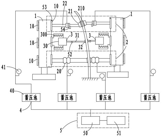
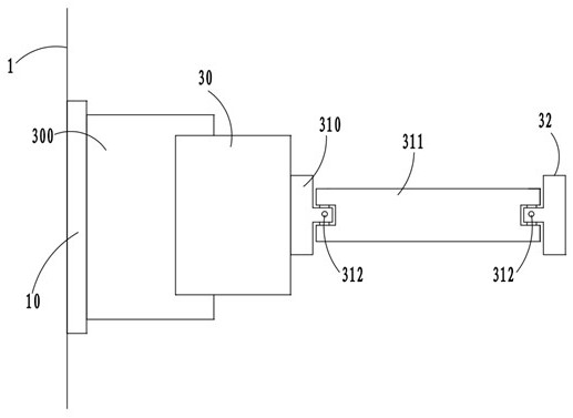
[0038] like figure 1 As shown in the figure, the combined static and vibration loading system of the aircraft airfoil used for the aircraft strength test includes a combined loading frame 1, a static loading assembly 2, a vibration loading assembly 3, an air source connection element 4 and a control element 5 that controls the normal operation of the entire system ;
[0039] The joint loading frame 1 is provided with a mounting member 10 for mounting the static loading assembly 2 and the vibration loading assembly 3;
[0040] The static loading assembly 2 includes two sets of first loading airbags 20 which are respectively located on both sides of the aircraft wing surface and statically load the position of the aircraft wing surface close to the root, and the two sets are respectively located on both sides of the aircraft wing surface and are close to the aircraft wing surface. The second loading air bag 21 is statically loaded at the wingtip position. The side of the second...
Embodiment 2
[0050] This embodiment differs from Embodiment 1 in that:
[0051] The structure of the negative pressure suction cup 32 is:
[0052] like Image 6 As shown, it includes a mounting portion 320 connected to the excitation rod 311, a negative pressure elastic tube 321 that is inserted into the mounting portion 320 on one side and connected to an external negative pressure source and has a corrugated soft sleeve 3210 on the outside, and is clamped in the mounting portion 320. The negative pressure suction cup main body 322 on the other side of the negative pressure elastic tube 321 is provided with a negative pressure suction plate 323 on the side wall of the negative pressure suction cup main body 322. Each soft rubber sealing ring 324 is evenly provided with 8 negative pressure holes 3240;
[0053] like Figure 7 As shown, the diameters of the negative pressure holes 3240 on the same soft rubber sealing ring 324 are equal, and the diameters of the corresponding negative pres...
Embodiment 3
[0055] What this embodiment records is the loading method of the aircraft wing surface static force and vibration combined loading system for the aircraft strength test of the above-mentioned embodiment 2, comprising the following steps:
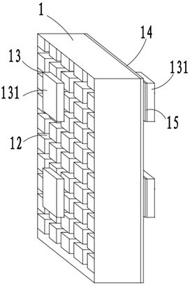
[0056] S1, measure the vertical distance between the joint loading frame 1 and the aircraft airfoil through the first displacement sensor 53, move the joint loading frame 1 to the set position, and adjust the static loading assembly 2 and the vibration loading through the mounting member 10 The specific adjustment process of the installation position of the component 3 on the aircraft wing surface is as follows: the adjustment installation plate 131 located on the rear side of the joint loading frame 1 is slid in the adjustment sliding port 12 through the external driving device, and at the same time, the I-shaped adjustment installation member 13 It also slides in the adjustment sliding port 12. When adjusted to the position that needs to be...
PUM
 Abstract
Description
Claims
Application Information
 - R&D
- Intellectual Property
- Life Sciences
- Materials
- Tech Scout
- Unparalleled Data Quality
- Higher Quality Content
- 60% Fewer Hallucinations
Browse by: Latest US Patents, China's latest patents, Technical Efficacy Thesaurus, Application Domain, Technology Topic, Popular Technical Reports.
© 2025 PatSnap. All rights reserved.Legal|Privacy policy|Modern Slavery Act Transparency Statement|Sitemap|About US| Contact US: help@patsnap.com


