Rapid pressurization system for spaceflight launching site

A technology of pressurization system and launch site, which is applied to non-pressure vessels, space navigation equipment, and equipment discharged from non-pressure vessels, etc. The effect of high pressure, rapid boost, atmospheric volume boost, and high-efficiency boost

Active Publication Date: 2022-06-28
XI AN JIAOTONG UNIV
View PDF8 Cites 0 Cited by
  • Summary
  • Abstract
  • Description
  • Claims
  • Application Information

AI Technical Summary

Problems solved by technology

In this technical field, there are no relevant application reports

Method used


Image

  • Rapid pressurization system for spaceflight launching site
  • Rapid pressurization system for spaceflight launching site
  • Rapid pressurization system for spaceflight launching site

Examples


Embodiment Construction

[0026] The present invention will be described in further detail below with reference to the embodiments and accompanying drawings.

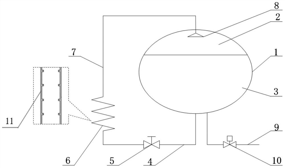
[0027] like figure 1 As shown, a rapid pressurization system for a space launch site includes a ground storage tank 1, the cryogenic liquid outlet of the ground storage tank 1 is connected to the inlet of a liquid inlet pipe 4, and the outlet of the liquid inlet pipe 4 is connected to the empty bath through a flow regulating valve 5. The inlet of the type vaporizer 6 is connected; the outlet of the air-bath vaporizer 6 is connected with the inlet of the return pipe 7, and the outlet of the return pipe 7 is connected with the energy dissipator 8 located in the top air pillow area 2 of the ground storage tank 1; the ground storage tank 1 The cryogenic liquid filling port is connected to the filling pipeline 9, and a regulating valve 10 is installed on the filling pipeline 9;

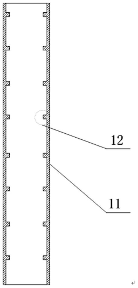
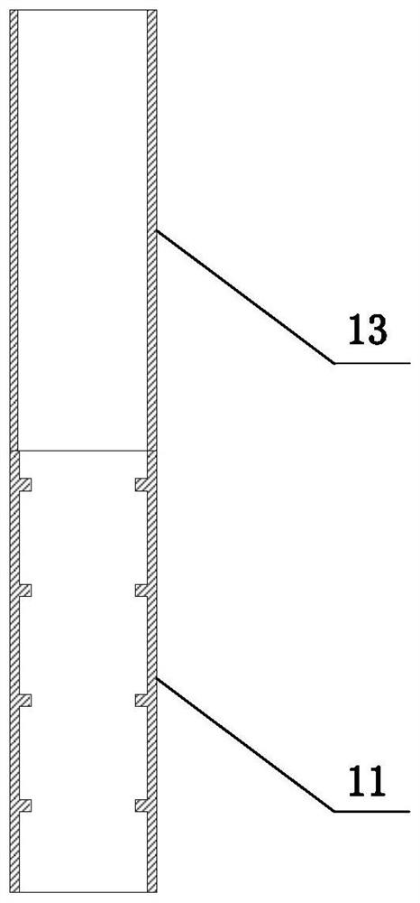
[0028] like figure 2 , image 3 As shown, the outer surface of the ...


PUM


Abstract

A spaceflight launching site rapid pressurization system comprises a ground storage tank, a low-temperature liquid outlet of the ground storage tank is connected with an inlet of a liquid inlet pipe, and an outlet of the liquid inlet pipe is connected with an inlet of an air bath type vaporizer through a flow adjusting valve; an outlet of the air bath type vaporizer is connected with an inlet of a return pipe, and an outlet of the return pipe is connected with an energy dissipater located in a top air pillow area of the ground storage tank; a low-temperature liquid filling port of the ground storage tank is connected with a filling pipeline, and a regulating valve is mounted on the filling pipeline; a heat exchange pipe section of the air bath type vaporizer is of an external light pipe or external star-shaped pipe structure, and an internal micro-ribbed pipe is arranged in the heat exchange pipe section. Or the front half part of the heat exchange pipe section adopts an inner micro rib pipe, and the rear half part adopts a straight pipe combination mode; the air bath type vaporizer is arranged at the bottommost part of the vertical ascending pipe or is arranged on the bottom horizontal pipe; the micro-ribs are adopted, the two-phase flow pipe section is shortened, the average fluid density of the vertical ascending pipe is reduced, pressurized gas is rapidly generated, and the arrangement and operation process of a self-pressurization system is simplified.

Description

technical field [0001] The invention relates to the technical field of low-temperature propellant filling in space launch sites, in particular to a rapid pressurization system for space launch sites. Background technique [0002] Low-temperature propellants have the advantages of high specific impulse, large thrust, non-toxicity, and no pollution, and have become the preferred propellants for space transportation and space flight. Before the launch vehicle is launched, the low-temperature propellant must be transferred from the ground storage tank to the storage tank on the rocket through the ground filling system. In the process of low-temperature propellant filling, the ground storage tank is usually pressurized, and a pressure difference is established between the ground storage tank and the storage tank on the arrow. Driven by the pressure difference, the extrusion transmission of low-temperature propellant is realized. Achieving rapid and stable pressurization of groun...

Claims


Application Information

Patent Timeline
IPC IPC(8): F17C9/02F17C13/00F17C13/04F16L9/02F16L59/065F16L59/02F28D21/00F28F1/40F28F21/08
CPCF17C9/02F17C13/004F17C13/04F16L9/006F16L59/065F16L59/02F16L9/02F28D21/00F28F1/40F28F21/083F28F21/084F17C2221/012F17C2221/011F17C2221/033F17C2205/0352F17C2205/0388F17C2227/0121F17C2227/0192F17C2270/0197F28D2021/0064
Inventor 王磊上官石厉彦忠谢福寿
Owner XI AN JIAOTONG UNIV
Why Eureka
Try Eureka