Solar yard lamp with camera device

A camera device and solar energy technology, which is applied to the components of lighting devices, lighting devices, and built-in power supplies, can solve the problems that solar garden lights cannot meet the needs of use, so as to ensure effectiveness and stability, quality assurance and Efficiency, the effect of ensuring efficiency

Pending Publication Date: 2022-06-28
广州宜易科技股份有限公司
View PDF0 Cites 0 Cited by
  • Summary
  • Abstract
  • Description
  • Claims
  • Application Information

AI Technical Summary

Problems solved by technology

[0004] In view of the above situation, in order to overcome the defects of the prior art, the present invention provides a solar garden light with a camera device, which effectively solves the problem that the existing solar garden lights with a camera device cannot meet the needs of people.

Method used


Image

  • Solar yard lamp with camera device
  • Solar yard lamp with camera device
  • Solar yard lamp with camera device

Examples


Embodiment 1

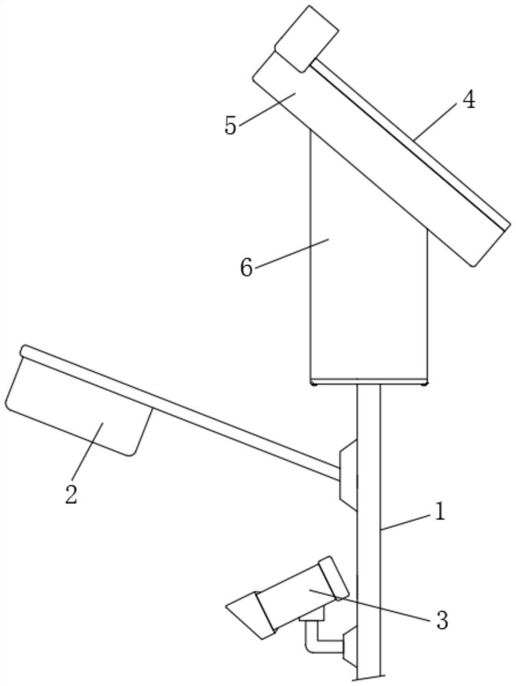
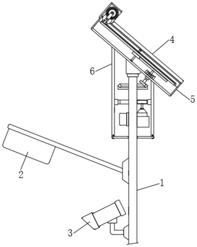
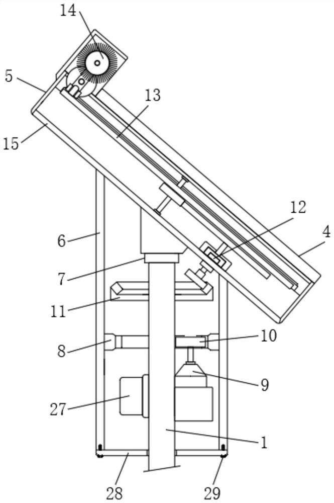
[0029] Example one, by Figure 1 to Figure 5 as well as Figure 7 to Figure 9Given, the present invention includes a light pole 1, a lighting lamp 2, a camera 3 and a solar photovoltaic panel 4, the lighting lamp 2 and the camera 3 are installed on the upper part of the light pole 1, the bottom of the solar photovoltaic panel 4 is installed with a fixed plate 5, the fixed plate A hollow cylindrical protective cover 6 is installed at the bottom of the 5, and a bearing 7 is installed at the bottom of the fixed plate 5. The bearing 7 is located inside the hollow cylindrical protective cover 6, and the bearing 7 is installed on the top of the light pole 1. A first inner gear 8 is installed inside, a motor 9 and a first transmission assembly 11 are installed on the surface of the light pole 1 located inside the hollow cylindrical protective cover 6, and a rotating gear 10 is installed at the output end of the motor 9. The ring gear 8 is meshed and connected, and through the arrang...

Embodiment 2

[0030] Embodiment 2, on the basis of Embodiment 1, by Figure 4 Give, Image 6 and Figure 9 Given, the second transmission assembly 12 includes a T-shaped connecting pin 1201, a round block 1202 and a fixed collar 1203, the T-shaped connecting pin 1201 and the fixed collar 1203 are installed at the bottom of the middle of the inverted H-shaped groove 15, and the round block 1202 is installed in Inside the fixing collar 1203, the top of the T-shaped connecting pin 1201 is mounted on the bottom of the round block 1202, the top of the circular block 1202 is mounted with a fixing pin 1204, and the top of the fixing pin 1204 extends to the top of the fixing collar 1203 and is installed with The large transmission gear 1205; the bottom of the round block 1202 is provided with a circular groove 12021, the upper part of the T-shaped connecting pin 1201 is installed in the interior of the circular groove 12021, and the surface of the upper part of the T-shaped connecting pin 1201 is ...

Embodiment 3

[0034] Embodiment 3, on the basis of embodiment 2, is made by Figure 4 , Figure 5 and Figure 7 Given, a rotating shaft 16 is installed in the middle of the rotating wheel 13, the rotating shaft 16 is installed in the middle of the inverted H-shaped groove 15, and the lower part of the rotating shaft 16 is installed with a second transmission gear 17, the second transmission gear 17 and the large transmission gear 1205 is meshed and connected, and a transmission bump 18 is installed on the edge of the top of the rotating round wheel 13, so that the rotation of the rotating round wheel 13 can be effectively adjusted; when the large transmission gear 1205 rotates, it will be driven by the second transmission gear 17. The rotating shaft 16 and the rotating round wheel 13 rotate, and the rotation of the rotating round wheel 13 will drive the transmission bump 18 to rotate in a circle; It extends to the inside of the inverted H-shaped groove 15, and a fixing bar 20 is connected...


PUM


Abstract

The invention relates to the technical field of solar garden lamps, and discloses a solar garden lamp with a camera device, which solves the problem that the existing solar garden lamp with the camera device cannot meet the use requirements of people, and comprises a lamp post, an illuminating lamp, a camera and a solar photovoltaic panel, the illuminating lamp and the camera are installed on the upper portion of the lamp pole, a fixing plate is installed at the bottom of a solar photovoltaic panel, a hollow cylindrical protective cover is installed at the bottom of the fixing plate, a bearing is installed at the bottom of the fixing plate, the bearing is located in the hollow cylindrical protective cover, and the bearing is installed at the top of the lamp pole. A first inner gear ring is mounted in the hollow cylindrical protective cover, and a motor and a first transmission assembly are mounted on the surface, located in the hollow cylindrical protective cover, of the lamp post; according to the solar garden lamp with the camera device, the angle of the photovoltaic panel can be adjusted, the cleaning mechanism is arranged, the use effectiveness and stability of the photovoltaic panel can be effectively guaranteed, and therefore the use efficiency of the garden lamp is guaranteed.

Description

technical field [0001] The invention belongs to the technical field of solar garden lights, in particular to a solar garden light with a camera device. Background technique [0002] Garden lights are widely used in garden scenic spots, cultural leisure and entertainment plazas, pedestrian streets, commercial streets, residential quarters, both sides of traffic lanes, etc., playing the dual role of decoration and lighting; garden lights are diverse and beautiful, and can be illuminated and beautified. Environment; while solar garden lights use sunlight to generate electricity during the day, and then store the generated electricity in the battery, and supply the electricity stored in the battery to the lighting device at night, and drive the lights of the lighting device to emit light to provide lighting, and the pillars are illuminated. At the same time, the existing solar garden lights are additionally installed with camera devices. Such solar garden lights not only have th...

Claims


Application Information

Patent Timeline
IPC IPC(8): F21S9/03F21V23/00H02S20/32H02S40/10
CPCF21S9/035F21V23/003H02S20/32H02S40/10Y02E10/50Y02B20/72
Inventor 侯佳玲林才渊吴斌胡斌斌
Owner 广州宜易科技股份有限公司
Why Eureka
Try Eureka