
Oil-immersed shunt reactor

A reactor and oil-immersed technology, applied in transformer/inductor cooling, transformer/inductor noise damping, spring/shock absorber, etc., can solve problems such as reducing the service life of reactors, human hearing damage, and aging of parts , achieve good sound insulation and shock absorption performance, accelerate heat dissipation effect, and prolong service life

Pending Publication Date: 2022-06-28
浙江富杰电气有限公司
View PDF0 Cites 0 Cited by
  • Summary
  • Abstract
  • Description
  • Claims
  • Application Information

AI Technical Summary

Problems solved by technology

The existing oil-immersed reactors will generate a lot of heat during use, which will lead to an increase in the overall temperature. The existing oil-immersed reactors have poor heat dissipation effect. If the heat generated by the oil-immersed reactors cannot Timely release will easily accelerate the consumption of insulating oil in the oil tank, and at the same time, it will accelerate the aging of some parts, resulting in damage to the reactor, thereby reducing the service life of the reactor, which cannot meet the use requirements
In addition, the vibration and noise of the oil-immersed reactor are relatively large, which will greatly damage the human hearing.

Method used


Image

  • Oil-immersed shunt reactor

Examples


Embodiment Construction

[0016] The present invention will be further described below in conjunction with the accompanying drawings:

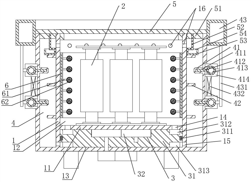
[0017] Refer to the attached figure 1 : The oil-immersed shunt reactor in this embodiment includes an oil tank 1 storing insulating oil and three parallel reactor units 2 arranged in the oil tank 1. The oil tank 1 is provided with a cooling device, and the cooling device includes The oil pump assembly 3 and the annular cooling tank 4 arranged on the periphery of the oil tank 1. The oil tank 1 is divided into an upper main oil cavity 12 and a lower auxiliary oil cavity 13 by setting the partition plate 11. The main oil cavity 12 and the auxiliary oil cavity 13 The reactor unit 2 and the oil pump assembly 3 are respectively installed inside. The oil pump assembly 3 includes an oil delivery plate 31 and a gear pump 32. A sealing ring 311 is provided between the oil delivery plate 31 and the inner wall of the auxiliary oil chamber 13. The oil delivery plate 31 The upper a...


PUM


Abstract

The invention discloses an oil-immersed shunt reactor which comprises an oil tank storing insulating oil and three shunt reactor units, a cooling device is arranged on the oil tank, the cooling device comprises an oil pump assembly and an annular cooling groove, and the interior of the oil tank is divided into a main oil cavity and an auxiliary oil cavity by arranging a partition plate. An electric reactor unit and an oil pump assembly are installed in the main oil cavity and the auxiliary oil cavity respectively, the oil pump assembly comprises an oil conveying plate and a gear pump, an outer annular heat dissipation baffle and an inner annular heat dissipation baffle are arranged in the annular cooling groove, and a zigzag cooling channel is formed between the outer annular heat dissipation baffle and the inner annular heat dissipation baffle. The oil-immersed shunt reactor is reasonable in design, insulating oil circularly flowing between the oil tank and the annular cooling groove is used for rapidly taking away heat generated by the reactor body, heat dissipation structures such as the outer annular heat dissipation baffles are matched to accelerate the heat dissipation effect and improve the heat dissipation efficiency, the oil-immersed shunt reactor has good sound insulation and shock absorption performance, the oil-immersed shunt reactor is not prone to damage, and the service life of the oil-immersed shunt reactor is prolonged. And the service life of the reactor is prolonged.

Description

technical field [0001] The invention relates to a reactor, in particular to an oil-immersed parallel reactor. Background technique [0002] There are a large number of harmonic sources such as rectification, current conversion, and frequency conversion devices in the power grid. The high-order harmonics generated by them will seriously endanger the safe operation of the main transformer and other electrical equipment in the system. Use reactors and capacitors in series to tune to a certain The resonant frequency is used to absorb the harmonic current of the corresponding frequency in the power grid, so as to ensure the safe operation of electrical equipment. Most of the existing oil-immersed filter reactors are composed of a fuel tank, a fuel tank cover, a reactor and a reactor bracket. The fuel tank is filled with With insulating oil, the reactor uses inductance to filter out harmonics. The existing oil-immersed reactor will generate a lot of heat during use, which will ca...

Claims


Application Information

Patent Timeline
IPC IPC(8): H01F27/12H01F27/14H01F27/22H01F27/08H01F27/33F16F15/023F16F15/04F16F15/02
CPCH01F27/12H01F27/14H01F27/22H01F27/08H01F27/33F16F15/023F16F15/04F16F15/02F16F15/022
Inventor 焦小斌余新火
Owner 浙江富杰电气有限公司
Learn More