
Device for removing glue and method for removing glue by using same

A connecting device and adhesive material technology, applied in the direction of cleaning methods using tools, cleaning methods and utensils, chemical instruments and methods, etc., can solve problems such as difficult operation, high time cost, and strong uncontrollable factors in manual glue removal operations. Achieve the effect of increasing the degree of automation, improving the efficiency of glue removal, and increasing the yield of rework

Pending Publication Date: 2022-07-01
YUYAO SUNNY OPTICAL INTELLIGENCE TECH CO LTD
View PDF9 Cites 0 Cited by
  • Summary
  • Abstract
  • Description
  • Claims
  • Application Information

AI Technical Summary

Problems solved by technology

The manual glue removal process is difficult to operate, and it takes a long time, the time cost is high, and the consumption of human and financial resources is huge
At the same time, the uncontrollable factors of manual deglue operation are strong, and it is easy to cause other parts to be scratched or cut accidentally due to personnel operation errors and scrapped.
Even, if similar parts are accidentally injured, if they are not found on the spot, it is more likely that the image module that misuses the damaged circuit board will become unusable later. In this way, in addition to the loss caused by the damaged circuit board, more waste will be wasted. Costs, including the assembly work of misusing the damaged circuit board as a component, other good components used in this assembly, and the cost of quality inspection after assembly, etc.
[0005] Therefore, in order to increase the repair yield of the image module and reduce the risks that may occur during the repair, so as to avoid unnecessary waste caused by mistakes, the present invention is dedicated to improving the problem of difficult glue removal and the corresponding problems in the repair process of the camera module. RISK OF DAMAGE TO PARTS

Method used


Image

  • Device for removing glue and method for removing glue by using same
  • Device for removing glue and method for removing glue by using same
  • Device for removing glue and method for removing glue by using same

Examples


Embodiment Construction

[0026] For a better understanding of the present application, various aspects of the present application will be described in more detail with reference to the accompanying drawings. It should be understood that these detailed descriptions are merely illustrative of exemplary embodiments of the present application and are not intended to limit the scope of the present application in any way. Throughout the specification, the same reference numerals refer to the same elements. The expression "and / or" includes any and all combinations of one or more of the associated listed items.

[0027] It should be noted that in this specification, the expressions first, second, third etc. are only used to distinguish one feature from another feature and do not imply any limitation on the feature.

[0028] It will also be understood that the terms "comprising", "including", "having", "comprising" and / or "comprising" when used in this specification mean the presence of stated features, eleme...


PUM


Abstract

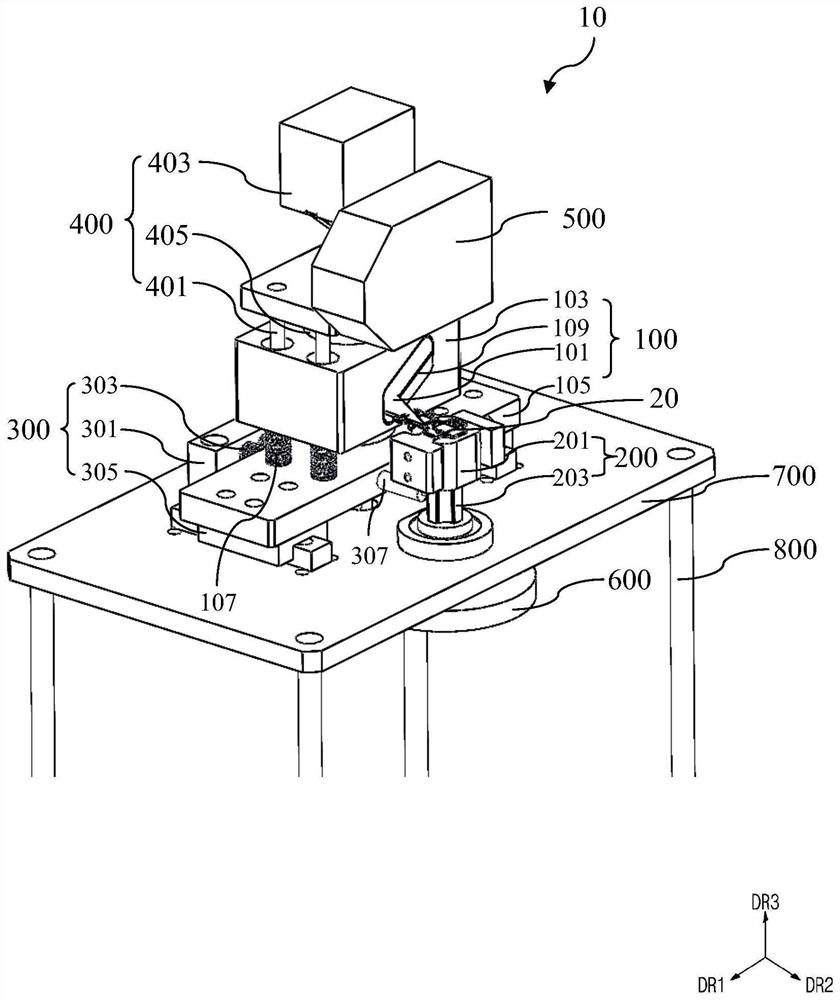
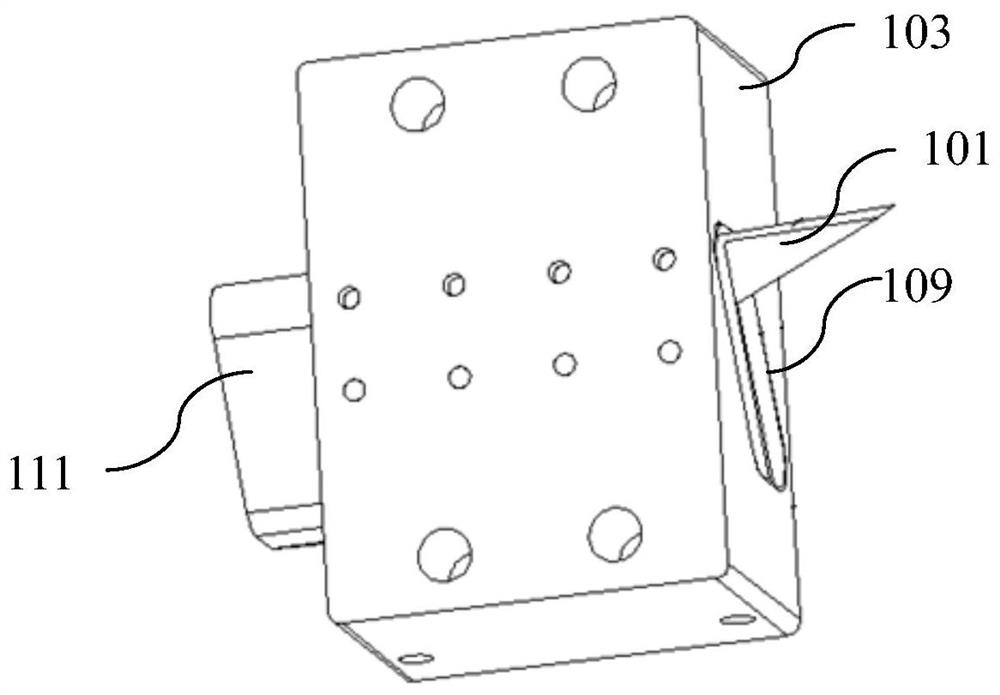
The invention provides a device for removing glue and a method for removing glue by using the device. The device for removing the glue comprises a blade assembly which comprises a blade for removing the glue material and a blade fixing part configured to fix the blade; the rotatable assembly comprises a glue removing operation table and a track limiting part located below the glue removing operation table, the device to be subjected to glue removing is fixed to the glue removing operation table, a glue material to be removed arranged on the device to be subjected to glue removing is exposed, and the rotatable assembly is configured to rotate relative to the blade assembly so that the glue material to be removed can be aligned with the blade and removed; and a coupling device configured to be coupled to the blade fixing portion and abut against an outer edge of the trajectory defining portion, the blade fixing portion moving along a trajectory corresponding to a shape of the outer edge of the trajectory defining portion through the coupling device. When observed from the top, the outer edge of the track limiting part is aligned with the outer edge of the to-be-removed rubber material and has the same shape as the to-be-removed rubber material.

Description

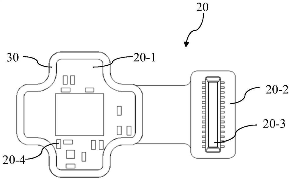
technical field [0001] The present application relates to a device for removing glue and a method for removing glue using the device. More specifically, the present application relates to a device for removing glue when a lens-type module is reworked and a method for removing glue using the device. Background technique [0002] In the manufacturing process of the optical camera module, there will inevitably be defective products with insufficient quality. Generally speaking, in order to reduce waste of resources, manufacturers will repair the defective products screened out during the quality inspection, so as to obtain a certain percentage of good products from them, so as to improve the overall yield rate and reduce the average production cost. [0003] During the repair work of the camera module, in order to repair or replace its parts, the motor that drives the lens and the circuit board are usually separated from each other, and then the residual glue on the circuit bo...

Claims


Application Information

Patent Timeline
Patent Type & Authority Applications(China)
IPC IPC(8): B08B1/00B08B1/04B08B13/00
CPCB08B13/00B08B2220/01B08B1/165B08B1/30B08B1/32
Inventor 潘周权韩华清徐杰伟孟垒垒
Owner YUYAO SUNNY OPTICAL INTELLIGENCE TECH CO LTD
Learn More